Telecom: UMTS
This article introduce the UMTS definded by 3GPP.
History
Refer to following links for UMTS history:
Standards
Refer to the table in section Specification Numbering for the UMTS standards, and the table in section 3GPP Standards for the UMTS features in each Release.
Network Structure
UMTS network includes following two parts:
| UMTS Radio access network | Universal Terrestrial Radio Access Network (UTRAN) |
| UMTS Core network | Mobile Application Part (MAP) |
The following figure shows the UMTS network structure, which is got from wikipedia:

And refer to following sections for the UMTS network structure in each Release:
- UMTS Network Architecture in R99
- UMTS Network Architecture in R4
- UMTS Network Architecture in R5
- UMTS Network Architecture in R6
- UMTS Network Architecture in R7
- UMTS Network Architecture in R8
- UMTS Network Architecture in R9
- UMTS Network Architecture in R10
- UMTS Network Architecture in R11
- UMTS Network Architecture in R12
- UMTS Network Architecture in R13
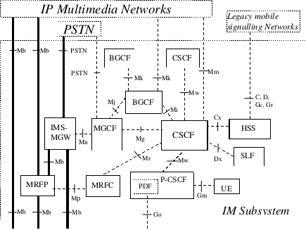
Refer to section Interfaces for details of interfaces in UMTS network. The following figures show the protocols used in different interfaces:
The following figure is UMTS domains and reference points from Rel-99_description_20160701:

R99 Network Structure
The following figure is UMTS and GSM Network Architecture from Rel-99_description_20160701:
Compare to R98, the entities in read blocks are new added.
R4 Network Structure
GSM Network Architecture
The following figure is Figure 1: GERAN reference architecture from TS 43.051-400 GSM/EDGE Radio Access Network (GERAN); Overall Description - Stage 2:
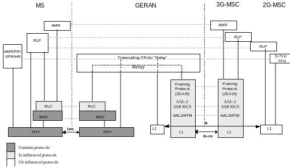
The following figure is Figure 4: User Plane protocols towards Packet Switched Core Network domain from TS 43.051-400 GSM/EDGE Radio Access Network (GERAN); Overall Description - Stage 2:
The following figure is Figure 5: Control Plane protocols towards Packet Switched Core Network domain from TS 43.051-400 GSM/EDGE Radio Access Network (GERAN); Overall Description - Stage 2:
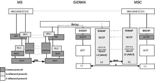
The following figure is Figure 6: User Plane protocols towards Circuit-Switched Core Network domain from TS 43.051-400 GSM/EDGE Radio Access Network (GERAN); Overall Description - Stage 2:
The following figure is Figure 7: Control Plane Protocols towards Circuit-Switched Core Network Domain from TS 43.051-400 GSM/EDGE Radio Access Network (GERAN); Overall Description - Stage 2:
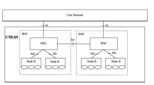
UMTS Network Architecture
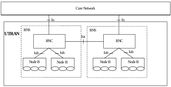
The following figure is Figure 4: UTRAN Architecture from TS 25.401-460 UTRAN overall description:
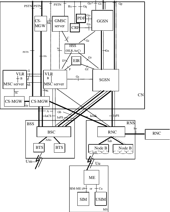
The following figure is Figure 1: Basic Configuration of a PLMN supporting CS and PS services and interfaces from TS 23.002-480 Network Architecture:
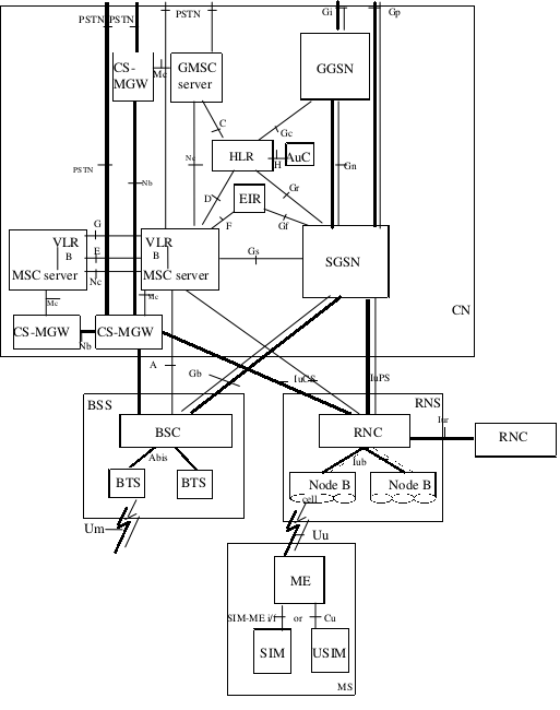
Compare to R99, the entity CS-MGW and corresponding interfaces are new added, and interface Iubis is renamed to Iub.
R5 Network Structure
The following figure is Figure 4: UTRAN Architecture from TS 25.401-5a0 UTRAN overall description:
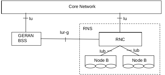
The following figure is Figure 4b: UTRAN and GERAN Iu mode connection with Iur-g from TS 25.401-5a0 UTRAN overall description:
The following figure is Figure 1: Basic Configuration of a PLMN supporting CS and PS services and interfaces from TS 23.002-5c0 Network Architecture:

Compare to R4, the entities HLR and AuC are merged into entity HSS, and interfaces IuCS and IuPS are new added to BSC.
R6 Network Structure
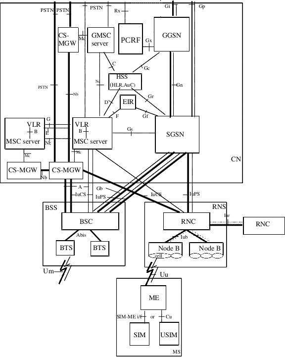
The following figure is Figure 1: Basic Configuration of a PLMN supporting CS and PS services and interfaces from TS 23.002-6a0 Network Architecture:
Compare to R5, the entities CRF (Charging Rules Function), PDF (Policy Decision Function) and corresponding interfaces are new added.
R7 Network Structure
The following figure is Figure 1: Basic Configuration of a PLMN supporting CS and PS services and interfaces from TS 23.002-760 Network Architecture:

Compare to R6, the entities PDF (Policy Decision Function) and CRF (Charging Rules Function) are merged into PCRF (Policy and Charging Rules Function).
R8 Network Structure
The following figure is Figure 1: Basic Configuration of a PLMN supporting CS and PS services and interfaces from TS 23.002-870 Network Architecture:

The network structure in R8 is the same to that in R7.
R9 Network Structure
The following figure is Figure 1: Basic Configuration of a PLMN supporting CS and PS services and interfaces from TS 23.002-960 Network Architecture:
The network structure in R9 is the same to that in R7 and R8.
R10 Network Structure
The following figure is Figure 1: Basic Configuration of a PLMN supporting CS and PS services and interfaces from TS 23.002-a30 Network Architecture:

The network structure in R10 is the same to that in R7, R8 and R9.
R11 Network Structure
The following figure is Figure 1: Basic Configuration of a PLMN supporting CS and PS services and interfaces from TS 23.002-b00 Network Architecture:

The network structure in R11 is the same to that in R7, R8, R9 and R10.
R12 Network Structure
The following figure is Figure 1: Basic Configuration of a PLMN supporting CS and PS services and interfaces from TS 23.002-c70 Network Architecture:

The network structure in R12 is the same to that in R7, R8, R9, R10 and R11.
R13 Network Structure
The following figure is Figure 1: Basic Configuration of a PLMN supporting CS and PS services and interfaces from TS 23.002-d50 Network Architecture:

The network structure in R13 is the same to that in R7, R8, R9, R10, R11 and R12.
Interfaces
The following table shows the interfaces in GSM/UMTS/LTE networks, refer to section 6 PLMN basic interfaces and reference points of TS 23.002-870 Network architecture:
| RAN | Interfaces | Connected_Entries | Protocol | Releases | Specs |
|---|---|---|---|---|---|
| UTRAN | Cu | USIM – ME | |||
| GERAN | Um | MS – BSS | TS 44-series, TS 45-series, TS 44.071 | ||
| UTRAN | Uu | UE – RNS | TS 24-series, TS 25-series, TS 25.305 | ||
| E-UTRAN | Uu | UE – E-UTRAN | TS 36-series | ||
| GERAN | Abis | BTS – BSC | TS 48.5xx-series | ||
| UTRAN | Iub | NodeB – RNC | TS 25.43x-series | ||
| UTRAN | Iur | RNC – RNC | TS 25.42x-series | ||
| E-UTRAN | X2 | eNB – eNB | TS 36.42x-series | ||
| GERAN | A | BSS – MSC | TS 48-series | ||
| GERAN | Gb | BSS – SGSN | TS 48.014, TS 48.016, TS 48.018 | ||
| GERAN | IuCS | BSS – MSC | RANAP | TS 25.41x-series | |
| GERAN | IuPS | BSS – SGSN | RANAP | TS 25.41x-series | |
| UTRAN | IuCS | RNS – MSC | RANAP | TS 25.41x-series | |
| UTRAN | IuPS | RNS – SGSN | RANAP | TS 25.41x-series | |
| UTRAN | Iupc | SRNC – SAS | TS 25.453 | ||
| E-UTRAN | S1-MME | E-UTRAN – MME | TS 36.41x-series, TS 24.301 | ||
| E-UTRAN | S1-U | E-UTRAN – S-GW | TS 29.274 | ||
| GERAN | B | MSC – VLR | Not standardised | ||
| GERAN | C | GMSC – HLR | MAP | TS 29.002, TS 23.078 | |
| GERAN UTRAN E-UTRAN |
D | HLR – VLR | MAP | TS 29.002, TS 23.078 | |
| GERAN UTRAN E-UTRAN |
E | MSC – MSC MSC – IP-SM-GW |
MAP | TS 29.002, TS 23.009 | |
| GERAN UTRAN E-UTRAN |
F | MSC – EIR | MAP | TS 29.002 | |
| GERAN UTRAN E-UTRAN |
G | VLR – VLR | MAP | TS 29.002 | |
| UTRAN | Mc | MSC – CS-MGW GMSC – CS-MGW |
H.248/IETF Megaco | ||
| UTRAN | Nc | MSC – GMSC | |||
| UTRAN | Nb | CS-MGW – CS-MGW | RTP/UDP/IP, or AAL2 | ||
| UTRAN | Gr | CS-MGW – CS-MGW | MAP, TCAP | TS 29.002 | |
| UTRAN | Gn | SGSN – GGSN (Intra PLMN) | UDP/IP | TS 29.060 | |
| UTRAN | Gp | SGSN – GGSN (Inter PLMN) | UDP/IP | TS 29.060 | |
| UTRAN | Gc | GGSN – HLR | MAP, TCAP | TS 29.002 | |
| UTRAN | Gf | SGSN – EIR | MAP, TCAP | TS 29.002 | |
| UTRAN | Gs | SGSN – MSC/VLR | SCCP, BSSAP+ | TS 29.016, TS 29.018 | |
| UTRAN | H | HLR/HSS – AuC | Not standardised | ||
| UTRAN | Gd | SGSN/IP-SM-GW – SMS-GMSC/SMS-IWMSC | MAP | TS 29.002 | |
| E-UTRAN | SGs | MSC/VLR – MME | SCTP | TS 23.272, TS 29.118 | |
| E-UTRAN | Sv | MSC/VLR – MME | TS 29.280 | ||
| E-UTRAN | S6a | MME – HSS | Diameter S6a/S6d | TS 29.272 | |
| E-UTRAN | S6d | SGSN – HSS | Diameter S6a/S6d | TS 29.272 | |
| E-UTRAN | S11 | MME – S-GW | TS 29.274 | ||
| E-UTRAN | S10 | MME – MME | TS 29.274 | ||
| E-UTRAN | S5/S8 | S-GW – PDN-GW | GTP, PMIP | TS 29.274, TS 29.275 | |
| E-UTRAN | S13 | MME – EIR | Diameter S13 | TS 29.272 | |
| E-UTRAN | S3 | MME – SGSN | TS 29.274 | ||
| E-UTRAN | S4 | S-GW – SGSN | TS 29.274 | ||
| E-UTRAN | S12 | S-GW – UTRAN | GTP-U | TS 29.274 | |
| E-UTRAN | S2a | Trusted non-3GPP IP Access – S-GW/P-GW | TS 29.275, TS 24.304 | ||
| E-UTRAN | S2b | PDN-GW/S-GW – ePDG | TS 29.275, TS 24.304 | ||
| E-UTRAN | S2c | UE – PDN-GW | TS 24.303 | ||
| E-UTRAN | S6b | 3GPP AAA Server/proxy – PDN-GW | TS 29.273 | ||
| E-UTRAN | SWa | 3GPP AAA Server/proxy – Untrusted non-3GPP IP Access | TS 29.273 | ||
| E-UTRAN | STa | 3GPP AAA Server/proxy – Trusted non-3GPP IP Access | TS 29.273 | ||
| E-UTRAN | SWd | 3GPP AAA Server – 3GPP AAA proxy | TS 29.273 | ||
| E-UTRAN | SWm | ePDG – 3GPP AAA Server/proxy | TS 29.273 | ||
| E-UTRAN | SWn | ePDG – Untrusted non-3GPP Access | TS 29.273 | ||
| E-UTRAN | SWu | ePDG – UE | TS 24.302 | ||
| E-UTRAN | SWx | HSS – 3GPP AAA Server | TS 29.273 | ||
| E-UTRAN | S14 | UE – ANDSF | TS 24.302 | ||
| E-UTRAN | S101 | HRDP AN – MME | TS 23.402, 3GPP2 C.S0087 0 | ||
| E-UTRAN | S102 | 3GPP2 1xCS IWF – MME | TS 23.216, TS 23.272, TS 23.402, 3GPP2 A.S0008-C | ||
| E-UTRAN | S103 | HSGW – S-GW | TS 23.402 | ||
| GETRAN | I | MSC – GCR | Not standardised | ||
| GETRAN | Lb | BSC – SMLC | TS 49.031 | ||
| GETRAN | Lp | SMLC – SMLC | BSSAPP-LE, SMLCPP | TS 49.031, TS 48.031 | |
| GETRAN | Le | GMLC – External LCS Client | MLP, OMA MLP TS, OSA-API | TS 29.198 | |
| GETRAN | Lr | GMLC – GMLC | RLP | ||
| GETRAN | GMSC – gsmSSF | TS 23.078 | |||
| GETRAN | gsmSSF – gsmSCF | TS 23.078 | |||
| GETRAN | gsmSSF – MSC | TS 23.078 | |||
| GETRAN | gsmSCF – HLR | TS 23.078 | |||
| GETRAN | gsmSCF – gsmSRF | TS 23.078 | |||
| GETRAN | gsmSCF – MSC | TS 23.078 | |||
| GETRAN | gprsSSF – SGSN | TS 23.078 | |||
| GETRAN | gprsSSF – gsmSCF | TS 23.078 | |||
| UTRAN | CBC – RNS | TS 25.41x-series | |||
| UTRAN | CBC – MME | TS 2x.xxx | |||
| UTRAN | NPDB – MSC | ||||
| UTRAN | MNP-SRF – GMSC | ||||
| UTRAN | MNP-SRF – HLR | ||||
| UTRAN | Cx | CSCF – HSS | TS 23.228 | ||
| UTRAN | Gm | CSCF – UE | SIP | RFC 3261 | |
| UTRAN | Mn | MGCF – IMS-MGW | |||
| UTRAN | Mg | MGCF – CSCF | SIP | RFC 3261 | |
| UTRAN | Cr | AS – MRFC | TS 23.218 | ||
| UTRAN | Mr | CSCF – MRFC | SIP | RFC 3261 | |
| UTRAN | Mp | MRFC – MRFP | |||
| UTRAN | Mw | CSCF – CSCF | |||
| UTRAN | ISC | CSCF – MRB | TS 23.218 | ||
| UTRAN | Rc | AS – MRB | TS 23.218 | ||
| UTRAN | Mi | CSCF – BGCF | SIP | ||
| UTRAN | Mj | BGCF – MGCF | SIP | ||
| UTRAN | Mk | BGCF/IBCF – BGCF | SIP | ||
| UTRAN | Dx | CSCF – SLF | TS 23.228 clause 5.8.1 | ||
| UTRAN | Mb | IPv6 network services | |||
| UTRAN | ISC | S-CSCF – AS | SIP | TS 23.228 clause 4.2.4 | |
| UTRAN | Sh | HSS – SIP AS or OSA SCS | SIP | TS 23.228 clause 4.2.4 | |
| UTRAN | Si | HSS – CAMEL IM-SSF | TS 23.228 clause 4.2.4 | ||
| UTRAN | Ut | UE – AS | TS 33.222 | ||
| UTRAN | Dh | AS – SLF | TS 23.228 clause 5.8.1 | ||
| UTRAN | Mx | CSCF/BGCF – IBCF | |||
| UTRAN | Ix | IBCF – TrGW | |||
| UTRAN | Ma | I-CSCF – AS | TS 23.228 clause 5.4.12, TS 23.228 clause 5.6.5.3 | ||
| UTRAN | Iq | P-CSCF – IMS Access Gateway | TS 23.228, Annex G | ||
| UTRAN | Ml | E-CSCF – LRF | |||
| UTRAN | Ici | IBCF – IBCF | |||
| UTRAN | Izi | TrGW – TrGW | |||
| UTRAN | I2 | MSC Server – CSCF | TS 23.292 | ||
| UTRAN | I3 | MSC Server – TAS | TS 23.292 | ||
| GERAN UTRAN |
D’/Gr’ | 3GPP AAA Server – HLR | TS 23.234 | ||
| UTRAN | Wa | WLAN access network – 3GPP AAA Proxy/Server | |||
| UTRAN | Wd | 3GPP AAA Server – 3GPP AAA Proxy | TS 23.234 | ||
| UTRAN | Wg | 3GPP AAA Server/Proxy – WAG | |||
| UTRAN | Wi | PDG – packet data networks | |||
| UTRAN | Wm | 3GPP AAA Server/Proxy – PDG | TS 23.234 | ||
| UTRAN | Wn | WAG – WLAN access network | |||
| UTRAN | Wp | WAG – PDG | |||
| UTRAN | Wu | WLAN UE – PDG | |||
| UTRAN | Ww | WLAN UE – WLAN access network | |||
| UTRAN | Wx | 3GPP AAA Server – HSS | TS 23.234 | ||
| UTRAN | Dw | 3GPP AAA Server – SLF | |||
| UTRAN | Gmb | GGSN – BM-SC | TS 23.246 | ||
| UTRAN | Rg | GUP Server – Applications | TS 23.240 | ||
| UTRAN | Rp | GUP Server – HSS Applications – HSS |
TS 23.240 | ||
| UTRAN | Gx | PCEF – PCRF/H-PCRF/V-PCRF | TS 29.212 | ||
| UTRAN | Rx | PCRF – Application Function | TS 23.203 | ||
| UTRAN | Sp | SPR – PCRF | |||
| UTRAN | Gy | OCS – PCEF | TS 32.251, RFC 4006 | ||
| UTRAN | Gz | OFCS – PCEF | TS 32.295 | ||
| UTRAN | Gxa | Trusted non-3GPP IP Access – PCRF/VPCRF | TS 29.21y | ||
| UTRAN | Gxb | ePDG – PCRF/VPCRF | |||
| UTRAN | Gxc | S-GW – PCRF/VPCRF | TS 29.21y | ||
| UTRAN | Gxx | PCRF/VPCRF – BBERF | TS 23.402, TS 23.203, TS 29.213 | ||
| UTRAN | S9 | HPCRF – VPCRF | TS 29.215 | ||
| UTRAN | J | IP-SM-GW – HSS | TS 23.204 | ||
| UTRAN | fixed networks – MSC | No. 7 User Parts TUP and ISUP | |||
| UTRAN | Gi | GGSN – packet data networks | |||
| UTRAN | SGi | PDN-GW – packet data networks | TS 29.061 | ||
| UTRAN | Le | GMLC – external LCS Client | |||
| UTRAN | Mm | CSCF/IBCF – Multimedia IP networks | |||
| UTRAN | Wi | PDG – packet data networks | |||
| UTRAN | Wn | WAG – WLAN access network |
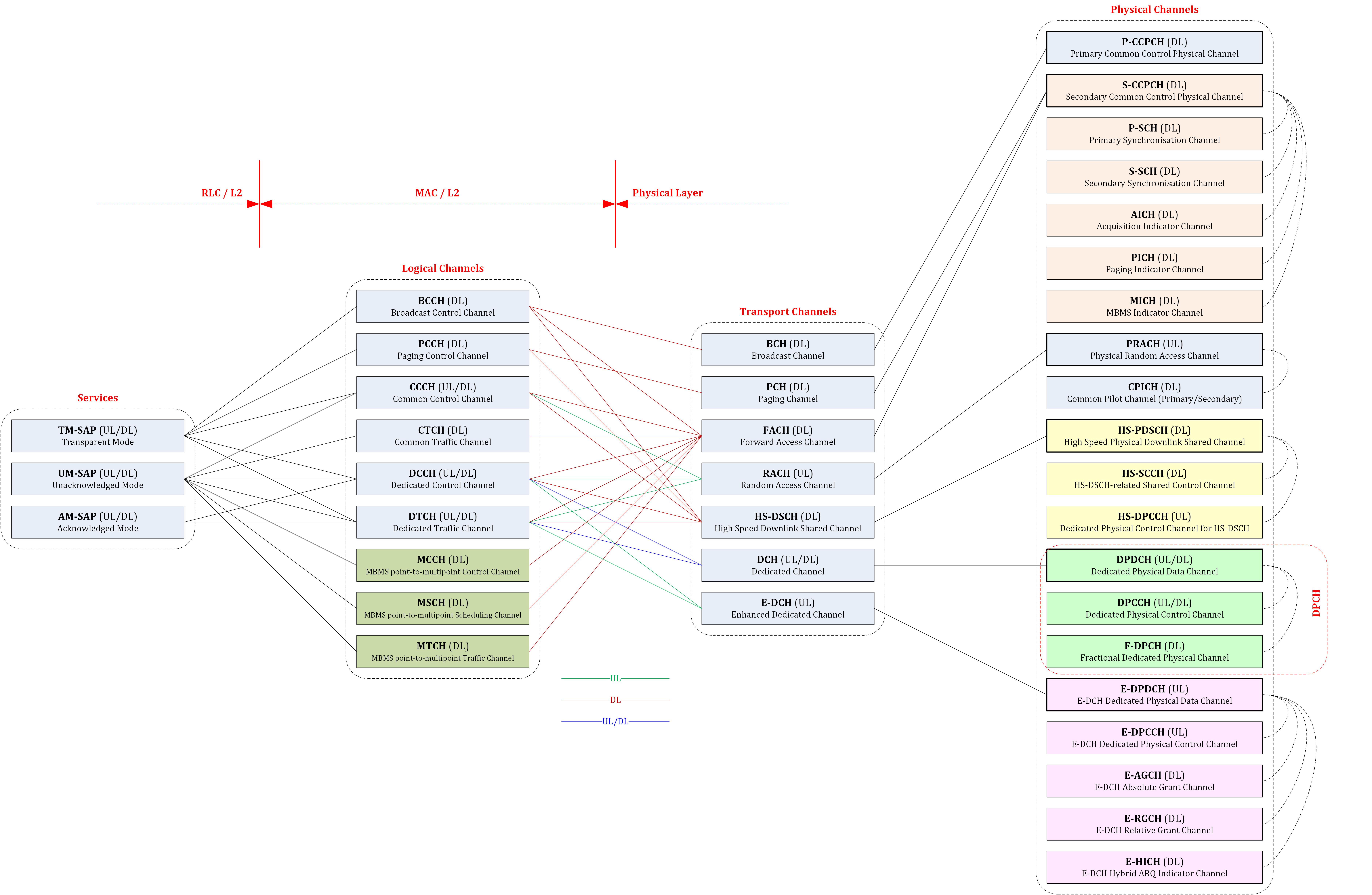
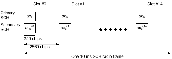
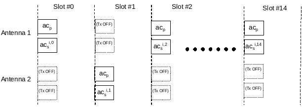
Channels
R99 Channels
UMTS Channels
Logical Channel
According to section 4.3.2 Logical Channels of TS 25.321-3h0 Medium Access Control (MAC) protocol specification, the MAC layer defines the following logical channels:
| Logical Channels | Type | FDD/TDD | UL/DL | Plane |
|---|---|---|---|---|
| Broadcast Control Channel (BCCH) | Control | FDD/TDD | DL | C-plane |
| Paging Control Channel (PCCH) | Control | FDD/TDD | DL | C-plane |
| Common Control Channel (CCCH) | Control | FDD/TDD | UL/DL | C-plane |
| Dedicated Control Channel (DCCH) | Control | FDD/TDD | UL/DL | C-plane |
| Shared Channel Control Channel (SHCCH) | Control | TDD | UL/DL | C-plane |
| Common Traffic Channel (CTCH) | Traffic | FDD/TDD | UL/DL | U-plane |
| Dedicated Traffic Channel (DTCH) | Traffic | FDD/TDD | UL/DL | U-plane |
Transport Channel
According to section 5.2 Layer 1 Services and Functions of TS 25.301-3b0 Radio Interface Protocol Architecture, the physical layer defines the following transport channels:
| Transport Channels | Type | FDD/TDD | UL/DL |
|---|---|---|---|
| Broadcast Channel (BCH) | Common | FDD/TDD | DL |
| Forward Access Channel (FACH) | Common | FDD/TDD | DL |
| Paging Channel (PCH) | Common | FDD/TDD | DL |
| Random Access Channel (RACH) | Common | FDD/TDD | UL |
| Common Packet Channel (CPCH) | Common | FDD | UL |
| Downlink Shared Channel (DSCH) | Common | TDD | DL |
| Uplink Shared Channel (USCH) | Common | TDD | UL |
| Dedicated Channel (DCH) | Dedicated | FDD/TDD | UL/DL |
Physical Channel
According to section 6 Mapping and association of physical channels of TS 25.211-3c0 Physical channels and mapping of transport channels onto physical channels (FDD), the Physical layer defines the following physical channels:
| Physical Channels | FDD/TDD | UL/DL |
|---|---|---|
| Primary Common Control Physical Channel (P-CCPCH) | FDD/TDD | DL |
| Secondary Common Control Physical Channel (S-CCPCH) | FDD/TDD | DL |
| Primary Synchronisation Channel (P-SCH) | FDD/TDD | DL |
| Secondary Synchronisation Channel (S-SCH) | FDD/TDD | DL |
| Physical Random Access Channel (PRACH) | FDD/TDD | UL |
| Physical Common Packet Channel (PCPCH) | FDD | UL |
| Primary Common Pilot Channel (P-CPICH) | FDD/TDD | DL |
| Secondary Common Pilot Channel (S-CPICH) | FDD/TDD | DL |
| Physical Downlink Shared Channel (PDSCH) | FDD/TDD | DL |
| Acquisition Indicator Channel (AICH) | FDD/TDD | DL |
| Access Preamble Acquisition Indicator Channel (AP-AICH) | ||
| Paging Indicator Channel (PICH) | FDD/TDD | DL |
| CPCH Status Indicator Channel (CSICH) | ||
| Collision-Detection/Channel-Assignment Indicator Channel (CD/CA-ICH) | ||
| Dedicated Physical Data Channel (DPDCH) | FDD/TDD | DL/UL |
| Dedicated Physical Control Channel (DPCCH) | FDD/TDD | DL/UL |
Channel Mapping
The following figure shows the channel mapping of logical channels, transport channels and physical channels:
R4 Channels
UMTS Channels
Logical Channel
According to section 4.3.2 Logical Channels of TS 25.321-4a0 Medium Access Control (MAC) protocol specification, the MAC layer defines the following logical channels:
| Logical Channels | Type | FDD/TDD | UL/DL | Plane |
|---|---|---|---|---|
| Broadcast Control Channel (BCCH) | Control | FDD/TDD | DL | C-plane |
| Paging Control Channel (PCCH) | Control | FDD/TDD | DL | C-plane |
| Common Control Channel (CCCH) | Control | FDD/TDD | UL/DL | C-plane |
| Dedicated Control Channel (DCCH) | Control | FDD/TDD | UL/DL | C-plane |
| Shared Channel Control Channel (SHCCH) | Control | TDD | UL/DL | C-plane |
| Common Traffic Channel (CTCH) | Traffic | FDD/TDD | UL/DL | U-plane |
| Dedicated Traffic Channel (DTCH) | Traffic | FDD/TDD | UL/DL | U-plane |
NOTE: The logical channels in R4 are the same with that in R99.
Transport Channel
According to section 5.2 Layer 1 Services and Functions of TS 25.301-440 Radio Interface Protocol Architecture, the Physical layer defines the following transport channels:
| Transport Channels | Type | FDD/TDD | UL/DL |
|---|---|---|---|
| Broadcast Channel (BCH) | Common | FDD/TDD | DL |
| Forward Access Channel (FACH) | Common | FDD/TDD | DL |
| Paging Channel (PCH) | Common | FDD/TDD | DL |
| Random Access Channel (RACH) | Common | FDD/TDD | UL |
| Common Packet Channel (CPCH) | Common | FDD | UL |
| Downlink Shared Channel (DSCH) | Common | TDD | DL |
| Uplink Shared Channel (USCH) | Common | TDD | UL |
| Dedicated Channel (DCH) | Dedicated | FDD/TDD | UL/DL |
NOTE: The transport channels in R4 are the same with that in R99.
Physical Channel
According to section 6 Mapping and association of physical channels of TS 25.211-460 Physical channels and mapping of transport channels onto physical channels (FDD), the Physical layer defines the following physical channels:
| Physical Channels | FDD/TDD | UL/DL | Reference |
|---|---|---|---|
| Primary Common Control Physical Channel (P-CCPCH) | FDD/TDD | DL | P-CCPCH |
| Secondary Common Control Physical Channel (S-CCPCH) | FDD/TDD | DL | S-CCPCH |
| Primary Synchronisation Channel (P-SCH) | FDD/TDD | DL | SCH |
| Secondary Synchronisation Channel (S-SCH) | FDD/TDD | DL | SCH |
| Physical Random Access Channel (PRACH) | FDD/TDD | UL | PRACH |
| Physical Common Packet Channel (PCPCH) | FDD | UL | |
| Primary Common Pilot Channel (P-CPICH) | FDD/TDD | DL | CPICH |
| Secondary Common Pilot Channel (S-CPICH) | FDD/TDD | DL | CPICH |
| Physical Downlink Shared Channel (PDSCH) | FDD/TDD | DL | |
| Acquisition Indicator Channel (AICH) | FDD/TDD | DL | AICH |
| Access Preamble Acquisition Indicator Channel (AP-AICH) | |||
| Paging Indicator Channel (PICH) | FDD/TDD | DL | PICH |
| CPCH Status Indicator Channel (CSICH) | |||
| Collision-Detection/Channel-Assignment Indicator Channel (CD/CA-ICH) | |||
| Dedicated Physical Data Channel (DPDCH) | FDD/TDD | DL/UL | DPDCH |
| Dedicated Physical Control Channel (DPCCH) | FDD/TDD | DL/UL | DPCCH |
NOTE: The physical channels in R4 are the same with that in R99.
Channel Mapping
The following figure shows the channel mapping of logical channels, transport channels and physical channels:
R5 Channels
UMTS Channels
Logical Channel
According to section 4.3.2 Logical Channels of TS 25.321-5e0 Medium Access Control (MAC) protocol specification, the MAC layer defines the following logical channels:
| Logical Channels | Type | FDD/TDD | UL/DL | Plane |
|---|---|---|---|---|
| Broadcast Control Channel (BCCH) | Control | FDD/TDD | DL | C-plane |
| Paging Control Channel (PCCH) | Control | FDD/TDD | DL | C-plane |
| Common Control Channel (CCCH) | Control | FDD/TDD | UL/DL | C-plane |
| Dedicated Control Channel (DCCH) | Control | FDD/TDD | UL/DL | C-plane |
| Shared Channel Control Channel (SHCCH) | Control | TDD | UL/DL | C-plane |
| Common Traffic Channel (CTCH) | Traffic | FDD/TDD | UL/DL | U-plane |
| Dedicated Traffic Channel (DTCH) | Traffic | FDD/TDD | UL/DL | U-plane |
NOTE: The logical channels in R5 are the same with that in R4.
Transport Channel
According to section 5.2 Layer 1 Services and Functions of TS 25.301-560 Radio Interface Protocol Architecture, the Physical layer defines the following transport channels:
| Transport Channels | Type | FDD/TDD | UL/DL |
|---|---|---|---|
| Broadcast Channel (BCH) | Common | FDD/TDD | DL |
| Forward Access Channel (FACH) | Common | FDD/TDD | DL |
| Paging Channel (PCH) | Common | FDD/TDD | DL |
| Random Access Channel (RACH) | Common | FDD/TDD | UL |
| Common Packet Channel (CPCH) | Common | FDD | UL |
| Downlink Shared Channel (DSCH) | Common | TDD | DL |
| Uplink Shared Channel (USCH) | Common | TDD | UL |
| High Speed Downlink Shared Channel (HS-DSCH) | Common | FDD/TDD | DL |
| Dedicated Channel (DCH) | Dedicated | FDD/TDD | UL/DL |
NOTE: The transport channel HS-DSCH is new added for HSDPA in R5.
Physical Channel
According to section 6 Mapping and association of physical channels of TS 25.211-580 Physical channels and mapping of transport channels onto physical channels (FDD), the Physical layer defines the following physical channels:
| Physical Channels | FDD/TDD | UL/DL |
|---|---|---|
| Primary Common Control Physical Channel (P-CCPCH) | FDD/TDD | DL |
| Secondary Common Control Physical Channel (S-CCPCH) | FDD/TDD | DL |
| Primary Synchronisation Channel (P-SCH) | FDD/TDD | DL |
| Secondary Synchronisation Channel (S-SCH) | FDD/TDD | DL |
| Acquisition Indicator Channel (AICH) | FDD/TDD | DL |
| Paging Indicator Channel (PICH) | FDD/TDD | DL |
| Physical Random Access Channel (PRACH) | FDD/TDD | UL |
| Primary Common Pilot Channel (P-CPICH) | FDD/TDD | DL |
| Secondary Common Pilot Channel (S-CPICH) | FDD/TDD | DL |
| Dedicated Physical Data Channel (DPDCH) | FDD/TDD | DL/UL |
| Dedicated Physical Control Channel (DPCCH) | FDD/TDD | DL/UL |
| High Speed Physical Downlink Shared Channel (HS-PDSCH) | FDD/TDD | DL |
| Shared Control Channel for HS-DSCH (HS-SCCH) | FDD/TDD | DL |
| Dedicated Physical Control Channel for HS-DSCH (HS-DPCCH) | FDD/TDD | UL |
NOTE1: The physical channels PDSCH, AP-AICH, CSICH and CD/CA-ICH are deleted from R5.
NOTE2: The physical channels HS-PDSCH, HS-SCCH and HS-DPCCH are new added for HSDPA in R5.
Channel Mapping
The following figure shows the channel mapping of logical channels, transport channels and physical channels:
R6 Channels
Logical Channel
According to section 4.3.2 Logical Channels of TS 25.321-6i0 Medium Access Control (MAC) protocol specification, the MAC layer defines the following logical channels:
| Logical Channels | Type | FDD/TDD | UL/DL | Plane |
|---|---|---|---|---|
| Broadcast Control Channel (BCCH) | Control | FDD/TDD | DL | C-plane |
| Paging Control Channel (PCCH) | Control | FDD/TDD | DL | C-plane |
| Common Control Channel (CCCH) | Control | FDD/TDD | UL/DL | C-plane |
| Dedicated Control Channel (DCCH) | Control | FDD/TDD | UL/DL | C-plane |
| Shared Channel Control Channel (SHCCH) | Control | TDD | UL/DL | C-plane |
| MBMS point-to-multipoint Control Channel (MCCH) | Control | FDD/TDD | UL/DL | C-plane |
| MBMS point-to-multipoint Scheduling Channel (MSCH) | Control | FDD/TDD | UL/DL | C-plane |
| Common Traffic Channel (CTCH) | Traffic | FDD/TDD | UL/DL | U-plane |
| Dedicated Traffic Channel (DTCH) | Traffic | FDD/TDD | UL/DL | U-plane |
| MBMS point-to-multipoint Traffic Channel (MTCH) | Traffic | FDD/TDD | UL/DL | U-plane |
NOTE: The logical channels MCCH, MSCH and MTCH are new added for MBMS in R6.
Transport Channel
According to section 5.2 Layer 1 Services and Functions of TS 25.301-660 Radio Interface Protocol Architecture, the Physical layer defines the following transport channels:
| Transport Channels | Type | FDD/TDD | UL/DL |
|---|---|---|---|
| Broadcast Channel (BCH) | Common | FDD/TDD | DL |
| Forward Access Channel (FACH) | Common | FDD/TDD | DL |
| Paging Channel (PCH) | Common | FDD/TDD | DL |
| Random Access Channel (RACH) | Common | FDD/TDD | UL |
| Common Packet Channel (CPCH) | Common | FDD | UL |
| Downlink Shared Channel (DSCH) | Common | TDD | DL |
| Uplink Shared Channel (USCH) | Common | TDD | UL |
| High Speed Downlink Shared Channel (HS-DSCH) | Common | FDD/TDD | DL |
| Dedicated Channel (DCH) | Dedicated | FDD/TDD | UL/DL |
| Enhanced Dedicated Channel (E-DCH) | Dedicated | FDD/TDD | UL |
NOTE: The transport channel E-DCH is new added for HSUPA in R6.
Physical Channel
According to section 6 Mapping and association of physical channels of TS 25.211-6a0 Physical channels and mapping of transport channels onto physical channels (FDD), the Physical layer defines the following physical channels:
| Physical Channels | FDD/TDD | UL/DL |
|---|---|---|
| Primary Common Control Physical Channel (P-CCPCH) | FDD/TDD | DL |
| Secondary Common Control Physical Channel (S-CCPCH) | FDD/TDD | DL |
| Primary Synchronisation Channel (P-SCH) | FDD/TDD | DL |
| Secondary Synchronisation Channel (S-SCH) | FDD/TDD | DL |
| Acquisition Indicator Channel (AICH) | FDD/TDD | DL |
| Paging Indicator Channel (PICH) | FDD/TDD | DL |
| MBMS Indicator Channel (MICH) | FDD/TDD | DL |
| Physical Random Access Channel (PRACH) | FDD/TDD | UL |
| Primary Common Pilot Channel (P-CPICH) | FDD/TDD | DL |
| Secondary Common Pilot Channel (S-CPICH) | FDD/TDD | DL |
| High Speed Physical Downlink Shared Channel (HS-PDSCH) | FDD/TDD | DL |
| Shared Control Channel for HS-DSCH (HS-SCCH) | FDD/TDD | DL |
| Dedicated Physical Control Channel for HS-DSCH (HS-DPCCH) | FDD/TDD | UL |
| Dedicated Physical Data Channel (DPDCH) | FDD/TDD | DL/UL |
| Dedicated Physical Control Channel (DPCCH) | FDD/TDD | DL/UL |
| Fractional Dedicated Physical Channel (F-DPCH) | FDD/TDD | DL/UL |
| E-DCH Dedicated Physical Data Channel (E-DPDCH) | FDD/TDD | UL |
| E-DCH Dedicated Physical Control Channel (E-DPCCH) | FDD/TDD | UL |
| E-DCH Absolute Grant Channel (E-AGCH) | FDD/TDD | DL |
| E-DCH Relative Grant Channel (E-RGCH) | FDD/TDD | DL |
| E-DCH Hybrid ARQ Indicator Channel (E-HICH) | FDD/TDD | DL |
NOTE: The physical channels MICH, F-DPCH, E-DPDCH, E-DPCCH, E-AGCH, E-RGCH and E-HICH are new added for HSUPA and MBMS in R6.
Channel Mapping
The following figure shows the channel mapping of logical channels, transport channels and physical channels:
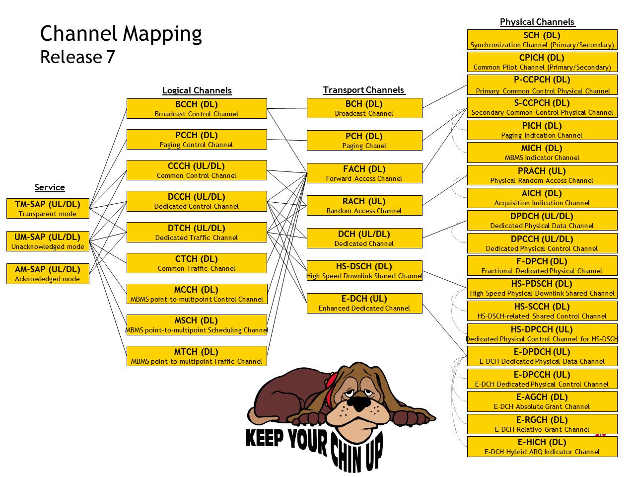
R7 Channels
UMTS Channels
Logical Channel
According to section 4.3.2 Logical Channels of TS 25.321-7j0 Medium Access Control (MAC) protocol specification, the MAC layer defines the following logical channels:
| Logical Channels | Type | FDD/TDD | UL/DL | Plane |
|---|---|---|---|---|
| Broadcast Control Channel (BCCH) | Control | FDD/TDD | DL | C-plane |
| Paging Control Channel (PCCH) | Control | FDD/TDD | DL | C-plane |
| Common Control Channel (CCCH) | Control | FDD/TDD | UL/DL | C-plane |
| Dedicated Control Channel (DCCH) | Control | FDD/TDD | UL/DL | C-plane |
| Shared Channel Control Channel (SHCCH) | Control | TDD | UL/DL | C-plane |
| MBMS point-to-multipoint Control Channel (MCCH) | Control | FDD/TDD | UL/DL | C-plane |
| MBMS point-to-multipoint Scheduling Channel (MSCH) | Control | FDD/TDD | UL/DL | C-plane |
| Common Traffic Channel (CTCH) | Traffic | FDD/TDD | UL/DL | U-plane |
| Dedicated Traffic Channel (DTCH) | Traffic | FDD/TDD | UL/DL | U-plane |
| MBMS point-to-multipoint Traffic Channel (MTCH) | Traffic | FDD/TDD | UL/DL | U-plane |
NOTE: The logical channels in R7 are the same with that in R6.
Transport Channel
According to section 5.2 Layer 1 Services and Functions of TS 25.301-750 Radio Interface Protocol Architecture, the Physical layer defines the following transport channels:
| Transport Channels | Type | FDD/TDD | UL/DL |
|---|---|---|---|
| Broadcast Channel (BCH) | Common | FDD/TDD | DL |
| Forward Access Channel (FACH) | Common | FDD/TDD | DL |
| Paging Channel (PCH) | Common | FDD/TDD | DL |
| Random Access Channel (RACH) | Common | FDD/TDD | UL |
| Common Packet Channel (CPCH) | Common | FDD | UL |
| Downlink Shared Channel (DSCH) | Common | TDD | DL |
| Uplink Shared Channel (USCH) | Common | TDD | UL |
| High Speed Downlink Shared Channel (HS-DSCH) | Common | FDD/TDD | DL |
| Dedicated Channel (DCH) | Dedicated | FDD/TDD | UL/DL |
| Enhanced Dedicated Channel (E-DCH) | Dedicated | FDD/TDD | UL |
NOTE: The transport channels in R7 are the same with that in R6.
Physical Channel
According to section 6 Mapping and association of physical channels of TS 25.211-7a0 Physical channels and mapping of transport channels onto physical channels (FDD), the Physical layer defines the following physical channels:
| Physical Channels | FDD/TDD | UL/DL |
|---|---|---|
| Primary Common Control Physical Channel (P-CCPCH) | FDD/TDD | DL |
| Secondary Common Control Physical Channel (S-CCPCH) | FDD/TDD | DL |
| Primary Synchronisation Channel (P-SCH) | FDD/TDD | DL |
| Secondary Synchronisation Channel (S-SCH) | FDD/TDD | DL |
| Acquisition Indicator Channel (AICH) | FDD/TDD | DL |
| Paging Indicator Channel (PICH) | FDD/TDD | DL |
| MBMS Indicator Channel (MICH) | FDD/TDD | DL |
| Physical Random Access Channel (PRACH) | FDD/TDD | UL |
| Primary Common Pilot Channel (P-CPICH) | FDD/TDD | DL |
| Secondary Common Pilot Channel (S-CPICH) | FDD/TDD | DL |
| High Speed Physical Downlink Shared Channel (HS-PDSCH) | FDD/TDD | DL |
| Shared Control Channel for HS-DSCH (HS-SCCH) | FDD/TDD | DL |
| Dedicated Physical Control Channel for HS-DSCH (HS-DPCCH) | FDD/TDD | UL |
| Dedicated Physical Data Channel (DPDCH) | FDD/TDD | DL/UL |
| Dedicated Physical Control Channel (DPCCH) | FDD/TDD | DL/UL |
| Fractional Dedicated Physical Channel (F-DPCH) | FDD/TDD | DL/UL |
| E-DCH Dedicated Physical Data Channel (E-DPDCH) | FDD/TDD | UL |
| E-DCH Dedicated Physical Control Channel (E-DPCCH) | FDD/TDD | UL |
| E-DCH Absolute Grant Channel (E-AGCH) | FDD/TDD | DL |
| E-DCH Relative Grant Channel (E-RGCH) | FDD/TDD | DL |
| E-DCH Hybrid ARQ Indicator Channel (E-HICH) | FDD/TDD | DL |
NOTE: The physical channels in R7 are the same with that in R6.
Channel Mapping
The following figure shows the channel mapping of logical channels, transport channels and physical channels:
R8 Channels
UMTS Channels
Logical Channel
According to section 4.3.2 Logical Channels of TS 25.321-8g0 Medium Access Control (MAC) protocol specification, the MAC layer defines the following logical channels:
| Logical Channels | Type | FDD/TDD | UL/DL | Plane |
|---|---|---|---|---|
| Broadcast Control Channel (BCCH) | Control | FDD/TDD | DL | C-plane |
| Paging Control Channel (PCCH) | Control | FDD/TDD | DL | C-plane |
| Common Control Channel (CCCH) | Control | FDD/TDD | UL/DL | C-plane |
| Dedicated Control Channel (DCCH) | Control | FDD/TDD | UL/DL | C-plane |
| Shared Channel Control Channel (SHCCH) | Control | TDD | UL/DL | C-plane |
| MBMS point-to-multipoint Control Channel (MCCH) | Control | FDD/TDD | UL/DL | C-plane |
| MBMS point-to-multipoint Scheduling Channel (MSCH) | Control | FDD/TDD | UL/DL | C-plane |
| Common Traffic Channel (CTCH) | Traffic | FDD/TDD | UL/DL | U-plane |
| Dedicated Traffic Channel (DTCH) | Traffic | FDD/TDD | UL/DL | U-plane |
| MBMS point-to-multipoint Traffic Channel (MTCH) | Traffic | FDD/TDD | UL/DL | U-plane |
NOTE: The logical channels in R8 are the same with that in R7.
Transport Channel
According to section 5.2 Layer 1 Services and Functions of TS 25.301-750 Radio Interface Protocol Architecture, the Physical layer defines the following transport channels:
| Transport Channels | Type | FDD/TDD | UL/DL |
|---|---|---|---|
| Broadcast Channel (BCH) | Common | FDD/TDD | DL |
| Forward Access Channel (FACH) | Common | FDD/TDD | DL |
| Paging Channel (PCH) | Common | FDD/TDD | DL |
| Random Access Channel (RACH) | Common | FDD/TDD | UL |
| Downlink Shared Channel (DSCH) | Common | TDD | DL |
| Uplink Shared Channel (USCH) | Common | TDD | UL |
| High Speed Downlink Shared Channel (HS-DSCH) | Common | FDD/TDD | DL |
| Enhanced Dedicated Channel (E-DCH) | Common [NOTE1] |
FDD/1.28 Mcps TDD | UL |
| Dedicated Channel (DCH) | Dedicated | FDD/TDD | UL/DL |
| Enhanced Dedicated Channel (E-DCH) | Dedicated [NOTE2] |
FDD/TDD | UL |
[NOTE1] RRC state: CELL_FACH state, IDLE mode
[NOTE2] RRC state: CELL_DCH
NOTE: The transport channel E-DCH (Common type) is the new added in R8.
Physical Channel
According to section 6 Mapping and association of physical channels of TS 25.211-870 Physical channels and mapping of transport channels onto physical channels (FDD), the Physical layer defines the following physical channels:
| Physical Channels | FDD/TDD | UL/DL |
|---|---|---|
| Primary Common Control Physical Channel (P-CCPCH) | FDD/TDD | DL |
| Secondary Common Control Physical Channel (S-CCPCH) | FDD/TDD | DL |
| Primary Synchronisation Channel (P-SCH) | FDD/TDD | DL |
| Secondary Synchronisation Channel (S-SCH) | FDD/TDD | DL |
| Acquisition Indicator Channel (AICH) | FDD/TDD | DL |
| Paging Indicator Channel (PICH) | FDD/TDD | DL |
| MBMS Indicator Channel (MICH) | FDD/TDD | DL |
| Physical Random Access Channel (PRACH) | FDD/TDD | UL |
| Primary Common Pilot Channel (P-CPICH) | FDD/TDD | DL |
| Secondary Common Pilot Channel (S-CPICH) | FDD/TDD | DL |
| High Speed Physical Downlink Shared Channel (HS-PDSCH) | FDD/TDD | DL |
| Shared Control Channel for HS-DSCH (HS-SCCH) | FDD/TDD | DL |
| Dedicated Physical Control Channel for HS-DSCH (HS-DPCCH) | FDD/TDD | UL |
| Dedicated Physical Data Channel (DPDCH) | FDD/TDD | DL/UL |
| Dedicated Physical Control Channel (DPCCH) | FDD/TDD | DL/UL |
| Fractional Dedicated Physical Channel (F-DPCH) | FDD/TDD | DL/UL |
| E-DCH Dedicated Physical Data Channel (E-DPDCH) | FDD/TDD | UL |
| E-DCH Dedicated Physical Control Channel (E-DPCCH) | FDD/TDD | UL |
| E-DCH Absolute Grant Channel (E-AGCH) | FDD/TDD | DL |
| E-DCH Relative Grant Channel (E-RGCH) | FDD/TDD | DL |
| E-DCH Hybrid ARQ Indicator Channel (E-HICH) | FDD/TDD | DL |
NOTE: The physical channels in R8 are the same with that in R7.
Channel Mapping
The following figure shows the channel mapping of logical channels, transport channels and physical channels:
User Equipment (UE)
The following figure is Figure 2: PLMN Access Reference Configuration (UTRAN Iu mode or E-UTRAN) from TS 24.002-810 PLMN Access Reference Configuration:

The following figure is Figure 1a: Functional Model for the User Equipment from TS 23.101-400 General UMTS Architecture:

UE = USIM + ME
ME = MT + TE
ME: the phone
MT: Mobile Termination, that’s the radio transmitting/receiving device of phone
TE: Application within phone
According to section 3.1 Mobile Termination (MT) of TS 24.002-810 PLMN Access Reference Configuration, the MT performs the following functions:
- radio transmission termination;
- radio transmission channel management;
- terminal capabilities, including presentation of a man-machine interface to a user;
- speech encoding/decoding;
- error protection for all information sent across the radio path. This includes FEC (forward error correction) and, for signalling and user data (except for transparent data services), ARQ (automatic request for retransmission);
- flow control of signalling and mapping of user signalling to/from PLMN access signalling;
- flow control of user data (except for transparent data services) and mapping of flow control for asynchronous transparent data services;
- rate adaptation of user data (see 3GPP TS 44.021[14]) and data formatting for the transmission SAP (3GPP TS 25.322 [41]);
- multiple terminal support;
- mobility management.
The User Equipment (UE) related standards include:
-
TS 24.002 - PLMN Access Reference Configuration
- TS 25.304 - User Equipment (UE) procedures in idle mode and procedures for cell reselection in connected mode
- TS 25.305 - Stage 2 functional specification of User Equipment (UE) positioning in UTRAN
- TS 25.306 - UE Radio Access capabilities
- TS 25.307 - Requirements on User Equipments (UEs) supporting a release-independent frequency band
-
TR 25.859 - User Equipment (UE) positioning enhancements for 1.28 Mcps TDD
- TS 31.101 - UICC-terminal interface; Physical and logical characteristics
- TS 31.102 - Characteristics of the Universal Subscriber Identity Module (USIM) application
- TS 31.103 - Characteristics of the IP Multimedia Services Identity Module (ISIM) application
- TS 31.111 - Universal Subscriber Identity Module (USIM) Application Toolkit (USAT)
- TS 31.112 - Universal Subscriber Identity Module (USIM) Application Toolkit (USAT) interpreter architecture description
- TS 31.113 - Universal Subscriber Identity Module (USIM) Application Toolkit (USAT) interpreter byte codes
- TS 31.114 - Universal Subscriber Identity Module (USIM) Application Toolkit (USAT) interpreter protocol and administration
- TS 31.115 - Remote APDU Structure for (U)SIM Toolkit applications
- TS 31.116 - Remote APDU Structure for (Universal) Subscriber Identity Module (U)SIM Toolkit applications
- TS 31.120 - UICC-terminal interface; Physical, electrical and logical test specification
- TS 31.121 - UICC-terminal interface; Universal Subscriber Identity Module (USIM) application test specification
- TS 31.122 - Universal Subscriber Identity Module (USIM) conformance test specification
- TS 31.124 - Mobile Equipment (ME) conformance test specification; Universal Subscriber Identity Module Application Toolkit (USAT) conformance test specification
- TS 31.130 - (U)SIM Application Programming Interface (API); (U)SIM API for Java Card
- TS 31.131 - C-language binding to (U)SIM API
- TS 31.133 - IP Multimedia Services Identity Module (ISIM) Application Programming Interface (API); ISIM API for Java Card™
UMTS Radio Access Network (UTRAN)
UTRAN = RNC + Node B
Overview
- TS 23.101 - General Universal Mobile Telecommunications System (UMTS) Architecture
- TS 25.301 - Radio Interface Protocol Architecture
- TS 25.302 - Services provided by the physical layer
- TS 25.401 - UTRAN overall description
Radio Interface (Uu)
The following figure is Figure 1: Assumed UMTS Architecture from TS 25.301-870 Radio Interface Protocol Architecture:
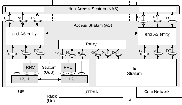
In the above figure, the Uu Stratum (UuS) block includes the radio interface protocol stack described in the following figure, which is Figure 2: Radio Interface protocol architecture (Service Access Points marked by circles) from TS 25.301-870 Radio Interface Protocol Architecture:
The radio interface is layered into three protocol layers:
- Physical Layer (L1)
- Data Link Layer (L2), which is split into following sublayers:
- Network Layer (L3)
The following figure is Figure 10: Interactions between RRC and lower layers from TS 25.301-870 Radio Interface Protocol Architecture. Also refer to section 10 Primitives of the physical layer of TS 25.302-870 Services provided by the physical layer and section 5.5 Interactions between RRC and lower layers in the C plane of TS 25.301-870 Radio Interface Protocol Architecture:
The following Primitives are used to layer-to-layer communication:
- Primitives between L1 and RRC/MAC
- Primitives between MAC and RRC/RLC
- Primitives between RLC and RRC/PDCP/BMC
- Primitives between PDCP and RRC/U-plane
- Primitives between BMC and RRC/U-plane
- Primitives between RRC and PHY/MAC/RLC/PDCP/BMC/U-plane
The following Protocol Data Units (PDU) are used to peer-to-peer communication:
- MAC peer-to-peer Communication
- RLC peer-to-peer Communication
- PDCP peer-to-peer Communication
- BMC peer-to-peer Communication
- RRC peer-to-peer Communication
Physical Layer (L1)
L1 Related Standards
TS 25.1xx - Uu Interface Radio Performance
- TS 25.101 - User Equipment (UE) radio transmission and reception (FDD)
- TS 25.102 - User Equipment (UE) radio transmission and reception (TDD)
- TS 25.104 - Base Station (BS) radio transmission and reception (FDD)
- TS 25.105 - Base Station (BS) radio transmission and reception (TDD)
-
TS 25.106 - UTRA repeater radio transmission and reception
- TS 25.111 - Location Measurement Unit (LMU) performance specification; User Equipment (UE) positioning in UTRAN
- TS 25.113 - Base Station (BS) and repeater ElectroMagnetic Compatibility (EMC)
- TS 25.133 - Requirements for support of radio resource management (FDD)
- TS 25.141 - Base Station (BS) conformance testing (FDD)
- TS 25.142 - Base Station (BS) conformance testing (TDD)
- TS 25.143 - UTRA repeater conformance testing
- TS 25.144 - User Equipment (UE) and Mobile Station (MS) over the air performance requirements
- TS 25.171 - Requirements for support of Assisted Global Positioning System (A-GPS) Frequency Division Duplex (FDD)
TS 25.2xx - Uu Interface Layer 1 (Physical Layer)
- TS 25.211 - Physical channels and mapping of transport channels onto physical channels (FDD)
- TS 25.212 - Multiplexing and channel coding (FDD)
- TS 25.213 - Spreading and modulation (FDD)
- TS 25.214 - Physical layer Procedures (FDD)
-
TS 25.215 - Physical layer Measurements (FDD)
- TS 25.221 - Physical channels and mapping of transport channels onto physical channels (TDD)
- TS 25.222 - Multiplexing and channel coding (TDD)
- TS 25.223 - Spreading and modulation (TDD)
- TS 25.224 - Physical layer Procedures (TDD)
- TS 25.225 - Physical layer Measurements (TDD)
L1 Services
According to section 5.2.1 L1 Services of TS 25.301-870 Radio Interface Protocol Architecture:
The physical layer (L1) offers information transfer services to MAC and higher layers. The physical layer transport services are described by how and with what characteristics data are transferred over the radio interface. An adequate term for this is Transport Channels.
Refer to TS 25.302-870 Services provided by the physical layer for more details of services provided by the physical layer (L1).
L1 Functions
According to section 5.2.2 L1 Functions of TS 25.301-870 Radio Interface Protocol Architecture, the physical layer (L1) performs the following main functions:
- Macrodiversity distribution/combining and soft handover execution;
- Error detection on transport channels and indication to higher layers;
- FEC encoding/decoding and interleaving/deinterleaving of transport channels;
- Multiplexing of transport channels and demultiplexing of coded composite transport channels (CCTrCH);
- Rate matching;
- Mapping of coded composite transport channels (CCTrCH) on physical channels;
- Power weighting and combining of physical channels;
- Modulation and spreading/demodulation and despreading of physical channels;
- Frequency and time (chip, bit, slot, frame) synchronisation;
- Measurements and indication to higher layers (e.g. FER, SIR, interference power, transmit power, etc.);
- Closed-loop power control;
- RF processing;
- Support of timing advance on uplink channels (TDD only);
- Support of Uplink Synchronisation as defined in TS 25.224 - Physical Layer Procedures (TDD) (TDD only).
Primitives between L1 and RRC/MAC
| Generic Name | Layers | Reference |
|---|---|---|
| CPHY-Sync-IND | PHY - RRC | TS 25.302-870 S10.2.1.1 |
| CPHY-Out-of-Sync-IND | PHY - RRC | TS 25.302-870 S10.2.1.2 |
| CPHY-Measurement-REQ | PHY - RRC | TS 25.302-870 S10.2.1.3 |
| CPHY-Measurement-IND | PHY - RRC | TS 25.302-870 S10.2.1.4 |
| CPHY-Error-IND | PHY - RRC | TS 25.302-870 S10.2.1.5 |
| CPHY-TrCH-Config-REQ | PHY - RRC | TS 25.302-870 S10.2.2.1 |
| CPHY-TrCH-Config-CNF | PHY - RRC | TS 25.302-870 S10.2.2.2 |
| CPHY-TrCH-Release-REQ | PHY - RRC | TS 25.302-870 S10.2.2.3 |
| CPHY-TrCH-Release-CNF | PHY - RRC | TS 25.302-870 S10.2.2.4 |
| CPHY-RL-Setup-REQ | PHY - RRC | TS 25.302-870 S10.2.2.5 |
| CPHY-RL-Setup-CNF | PHY - RRC | TS 25.302-870 S10.2.2.6 |
| CPHY-RL-Release-REQ | PHY - RRC | TS 25.302-870 S10.2.2.7 |
| CPHY-RL-Release-CNF | PHY - RRC | TS 25.302-870 S10.2.2.8 |
| CPHY-RL-Modify-REQ | PHY - RRC | TS 25.302-870 S10.2.2.9 |
| CPHY-RL-Modify-CNF | PHY - RRC | TS 25.302-870 S10.2.2.10 |
| CPHY-Commit-REQ | PHY - RRC | TS 25.302-870 S10.2.2.11 |
| CPHY-Out-of-Sync-Config-REQ | PHY - RRC | TS 25.302-870 S10.2.2.16 |
| CPHY-Out-of-Sync-Config-CNF | PHY - RRC | TS 25.302-870 S10.2.2.17 |
| CPHY-MBMS-Config-REQ | PHY - RRC | TS 25.302-870 S10.2.2.18 |
| CPHY-MBMS-Config-CNF | PHY - RRC | TS 25.302-870 S10.2.2.19 |
| PHY-Access-REQ | PHY - MAC | TS 25.302-870 S10.1.1 |
| PHY-Access-CNF | PHY - MAC | TS 25.302-870 S10.1.2 |
| PHY-Data-REQ | PHY - MAC | TS 25.302-870 S10.1.3 |
| PHY-Data-IND | PHY - MAC | TS 25.302-870 S10.1.4 |
| PHY-Status-IND | PHY - MAC | TS 25.302-870 S10.1.7 |
Transport Channels
A transport channel is defined by how and with what characteristics data is transferred over the air interface. A general classification of transport channels is into two groups:
- Dedicated channels, using inherent addressing of UE;
- Common channels, using explicit addressing of UE if addressing is needed.
| Transport Channels | Rel | Type | FDD/TDD | UL/DL |
|---|---|---|---|---|
| Broadcast Channel (BCH) | R99 | Common | FDD/TDD | DL |
| Forward Access Channel (FACH) | R99 | Common | FDD/TDD | DL |
| Paging Channel (PCH) | R99 | Common | FDD/TDD | DL |
| Random Access Channel (RACH) | R99 | Common | FDD/TDD | UL |
| Downlink Shared Channel (DSCH) | R99 | Common | TDD | DL |
| Uplink Shared Channel (USCH) | R99 | Common | TDD | UL |
| High Speed Downlink Shared Channel (HS-DSCH) | R5 | Common | FDD/TDD | DL |
| Enhanced Dedicated Channel (E-DCH) | R6 | Common [NOTE1] |
FDD/1.28 Mcps TDD | UL |
| Dedicated Channel (DCH) | R99 | Dedicated | FDD/TDD | UL/DL |
| Enhanced Dedicated Channel (E-DCH) | R6 | Dedicated [NOTE2] |
FDD/TDD | UL |
[NOTE1] RRC state: CELL_FACH state, IDLE mode
[NOTE2] RRC state: CELL_DCH
Refer to Logical Channels for channel mapping between Logical Channel, Transport Channel and Physical Channel.
Refer to Transport Channel Multiplexing/Coding for transport channel multiplexing structure.
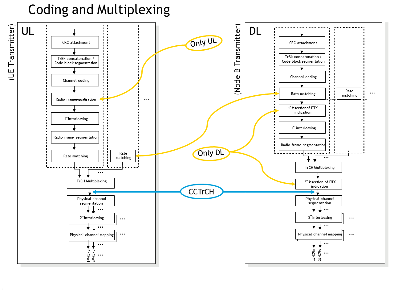
Transport Channel Multiplexing/Coding
Data stream from/to MAC and higher layers (Transport block / Transport block set) is encoded/decoded to offer transport services over the radio transmission link. Channel coding scheme is a combination of error detection, error correcting, rate matching, interleaving and transport channels mapping onto/splitting from physical channels.
General Channel Coding for TrCHs
The following channel coding scheme only applies to the transport channels: DCH, RACH, BCH, FACH and PCH.
The following figure is Figure 1: Transport channel multiplexing structure for uplink from TS 25.212-870 Multiplexing and channel coding (FDD):
The following figure is Figure 2: Transport channel multiplexing structure for downlink from TS 25.212-870 Multiplexing and channel coding (FDD):
The bit sequences output from DCH, RACH, BCH, FACH and PCH are mapped to DPDCH, PRACH, P-CCPCH and S-CCPCH.
Channel Coding for HS-DSCH
Data arrives to the coding unit in form of a maximum of one transport block once every transmission time interval. The transmission time interval is 2 ms which is mapped to a radio sub-frame of 3 slots. In the following figure, the number of transport blocks and the number of transport channels is always one i.e. m=1, i=1.
The following figure is Figure 16: Coding chain for HS-DSCH from TS 25.212-870 Multiplexing and channel coding (FDD):
The output bit sequence Rp,i is mapped to HS-PDSCH sub-frame, refer to HS-PDSCH.
Channel Coding for HS-SCCH
HS-SCCH Types:
-
HS-SCCH type 1 is used when the following two conditions are both true:
- the UE is not configured in MIMO mode, and
- the conditions for usage of HS-SCCH type 2 are not met.
-
HS-SCCH type 2 is used for HS-SCCH-less operation. HS-SCCH type 2 is not used when the UE is configured in MIMO mode. Refer to IE HS-SCCH less information.
-
HS-SCCH type 3 is used when the UE is configured in MIMO mode. Refer to IE MIMO parameters -> MIMO operation.
HS-SCCH orders are commands sent to the UE using HS-SCCH. No HS-PDSCH is associated with HS-SCCH orders. The coding for HS-SCCH orders is specified in:
- Figure 19: Coding chain for HS-SCCH type 1 for the case when the UE is not configured in MIMO mode; and
- Figure 19B: Coding chain for HS-SCCH type 3 for the case when the UE is configured in MIMO mode, with the exception of HS-DSCH serving cell change order, which is always transmitted using HS-SCCH type 1 specified in Figure 19: Coding chain for HS-SCCH type 1.
The following figure is Figure 19: Coding chain for HS-SCCH type 1 from TS 25.212-870 Multiplexing and channel coding (FDD):
The following figure is Figure 19A: Coding chain for HS-SCCH type 2 from TS 25.212-870 Multiplexing and channel coding (FDD):
The following figure is Figure 19B: Coding chain for HS-SCCH type 3 from TS 25.212-870 Multiplexing and channel coding (FDD):
The bit sequence S1,i, i=1..40 is mapped to the first slot of the HS-SCCH sub frame. The bit sequence R2,i, i=1..80 is mapped to the second and third slot of the HS-SCCH sub frame. Refer to HS-SCCH.
Channel Coding for HS-DPCCH
Data arrives to the coding unit in form of indicators for measurement indication and HARQ acknowledgement.
The following figure is Figure 20: Coding for HS-DPCCH when the UE is not configured in MIMO mode from TS 25.212-870 Multiplexing and channel coding (FDD):
The following figure is Figure 20A: Coding for HS-DPCCH when the UE is configured in MIMO mode from TS 25.212-870 Multiplexing and channel coding (FDD):
The bit sequences Wk and Bk are mapped to the corresponding HS-DPCCH sub-frame, refer to HS-DPCCH.
Channel Coding for E-DCH
Data arrives to the coding unit in form of a maximum of one transport block once every transmission time interval (TTI).
The following figure is Figure 21: Transport channel processing for E-DCH from TS 25.212-870 Multiplexing and channel coding (FDD):
The sequence of bits output from the E-DCH channel coding is mapped to the corresponding E-DPDCH sub-frame, refer to E-DPDCH.
Channel Coding for E-DPCCH
The following information is transmitted by means of the E-DPCCH: Retransmission sequence number (RSN), E-TFCI and Happy bit.
-
The happy bit Xh,1 is got from Table 16A: Mapping of “Happy” bit of TS 25.212-870 Multiplexing and channel coding (FDD);
-
The sequence Xtfci,i, i=1..7 is got from section 4.9.2.1 Information field mapping of E-TFCI of TS 25.212-870 Multiplexing and channel coding (FDD);
-
The sequence Xrsn,i, i=1..2 is determined by RSN in section 4.9.2.2 Information field mapping of retransmission sequence number of TS 25.212-870 Multiplexing and channel coding (FDD).
NOTE: The parameter s and r is determined by E-DCH RV Index according to Table 15D: RV for E-DCH of TS 25.212-870 Multiplexing and channel coding (FDD), where the E-DCH RV Index is determined by following parameters:
- The RV Configuration from IE HARQ Info for E-DCH -> HARQ RV Configuration;
- RSN Value reported to UTRAN;
- Nsys / Ne,data,j calculated in section 4.8.4 Physical layer HARQ functionality and rate matching for E-DCH of TS 25.212-870 Multiplexing and channel coding (FDD);
- Table 16: Relation between RSN value and E-DCH RV Index of TS 25.212-870 Multiplexing and channel coding (FDD).
-
The sequences Xh,1, Xrsn,i and Xtfci,i are encoded by the following figure.
The following figure is Figure 23: Coding chain for E-DPCCH from TS 25.212-870 Multiplexing and channel coding (FDD):
The sequence of bits Zi, i=1..29 output from the E-DPCCH channel coding is mapped to the corresponding E-DPCCH sub-frame. The bits are mapped so that they are transmitted over the air in ascending order with respect to i. If the E-DCH TTI is equal to 10 ms the sequence of bits is transmitted in all the E-DPCCH sub frames of the E-DPCCH radio frame. Refer to E-DPCCH.
Channel Coding for E-AGCH
-
Select Table 16B or Table 16B.1 of TS 25.211-870 Physical channels and mapping of transport channels onto physical channels (FDD) according to IE UL 16QAM configuration -> UL 16QAM settings;
-
The sequence Xagv,i, i=1..5 is got from column Index in Table 16B or Table 16B.1, which is choose in (1);
-
The sequence Get Xags,1 is got from Table 16C: Mapping of Absolute Grant Scope of TS 25.212-870 Multiplexing and channel coding (FDD);
-
Then, the sequences Xagv,i, i=1..5 and Xags,1 are encoded by the following figure.
The following figure is Figure 24: Coding for E-AGCH from TS 25.212-870 Multiplexing and channel coding (FDD):
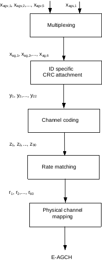
Also refer to E-AGCH.
Mapping for E-RGCH Relative Grant
-
The parameter a is got from column RG Value in Table 17: Mapping of RG value of TS 25.212-870 Multiplexing and channel coding (FDD);
-
The Sequence index l is got from IE E-RGCH Info -> Signature Sequence;
-
The sequence m(i), i=0..39 is got from Table 16B: E-HICH and E-RGCH signature hopping pattern of TS 25.211-870 Physical channels and mapping of transport channels onto physical channels (FDD), according to Sequence index l in (2).
-
The sequence bi,0, i=0..39 is calculated by:
- Formula in section 5.3.2.4 E-DCH Relative Grant Channel and Table 16A: E-RGCH and E-HICH signature sequences of TS 25.211-870 Physical channels and mapping of transport channels onto physical channels (FDD), and
- Parameter a in (1).
-
Then, the sequence bi,0, i=0..39 is transmitted on E-RGCH according to Figure 12A: E-RGCH and E-HICH structure from TS 25.211-870 Physical channels and mapping of transport channels onto physical channels (FDD), refer to E-RGCH.
Mapping for E-HICH ACK/NACK
-
The parameter a is got from column HARQ acknowledgement indicator in Table 18: Mapping of HARQ Acknowledgement of TS 25.212-870 Multiplexing and channel coding (FDD);
-
The Sequence index l is got from IE E-HICH Info -> Signature Sequence;
-
The sequence m(i), i=0..39 is got from Table 16B: E-HICH and E-RGCH signature hopping pattern of TS 25.211-870 Physical channels and mapping of transport channels onto physical channels (FDD), according to Sequence index l in (2).
-
The sequence bi,0, i=0..39 is calculated by:
- Formula in section 5.3.2.5 E-DCH Hybrid ARQ Indicator Channel and Table 16A: E-RGCH and E-HICH signature sequences of TS 25.211-870 Physical channels and mapping of transport channels onto physical channels (FDD), and
- Parameter a in (1).
-
Then, the sequence bi,0, i=0..39 is transmitted on E-HICH according to Figure 12A: E-RGCH and E-HICH structure of TS 25.211-870 Physical channels and mapping of transport channels onto physical channels (FDD):, refer to E-HICH.
Physical Channels
Refer to section 6.1 Mapping of transport channels onto physical channels of TS 25.211-870 Physical channels and mapping of transport channels onto physical channels (FDD) for mapping of transport channels onto physical channels.
Refer to Logical Channels for channel mapping between Logical Channel, Transport Channel and Physical Channel.
Physical channels are defined by a specific carrier frequency, scrambling code, channelization code (optional), time start & stop (giving a duration) and, on the uplink, relative phase (0 or π/2). The downlink E-HICH and E-RGCH are each further defined by a specific orthogonal signature sequence. Scrambling and channelization codes are specified in TS 25.213-850 Spreading and modulation (FDD). Time durations are defined by start and stop instants, measured in integer multiples of chips. Suitable multiples of chips also used in specification are:
| Durations | Length (subframe) |
Length (slots) |
Length (chips) |
Description |
|---|---|---|---|---|
| Frame | 5 | 15 | 38400 | A radio frame is a processing duration which consists of 15 slots. The length of a radio frame corresponds to 38400 chips. |
| Subframe | 1 | 3 | 7680 | A sub-frame is the basic time interval for E-DCH and HS-DSCH transmission and E-DCH and HS-DSCH-related signalling at the physical layer. The length of a sub-frame corresponds to 3 slots (7680 chips). |
| Slot | 1 | 2560 | A slot is a duration which consists of fields containing bits. The length of a slot corresponds to 2560 chips. |
The physical channels are:
| Physical Channels | FDD/TDD | UL/DL | Reference |
|---|---|---|---|
| Primary Common Control Physical Channel (P-CCPCH) | FDD/TDD | DL | P-CCPCH |
| Secondary Common Control Physical Channel (S-CCPCH) | FDD/TDD | DL | S-CCPCH |
| Primary Synchronisation Channel (P-SCH) | FDD/TDD | DL | SCH |
| Secondary Synchronisation Channel (S-SCH) | FDD/TDD | DL | SCH |
| Acquisition Indicator Channel (AICH) | FDD/TDD | DL | AICH |
| Paging Indicator Channel (PICH) | FDD/TDD | DL | PICH |
| MBMS Indicator Channel (MICH) | FDD/TDD | DL | MICH |
| Physical Random Access Channel (PRACH) | FDD/TDD | UL | PRACH |
| Primary Common Pilot Channel (P-CPICH) | FDD/TDD | DL | CPICH |
| Secondary Common Pilot Channel (S-CPICH) | FDD/TDD | DL | CPICH |
| High Speed Physical Downlink Shared Channel (HS-PDSCH) | FDD/TDD | DL | HS-PDSCH |
| Shared Control Channel for HS-DSCH (HS-SCCH) | FDD/TDD | DL | HS-SCCH |
| Dedicated Physical Control Channel for HS-DSCH (HS-DPCCH) | FDD/TDD | UL | HS-DPCCH |
| Dedicated Physical Data Channel (DPDCH) | FDD/TDD | DL/UL | DPDCH |
| Dedicated Physical Control Channel (DPCCH) | FDD/TDD | DL/UL | DPCCH |
| Fractional Dedicated Physical Channel (F-DPCH) | FDD/TDD | DL/UL | F-DPCH |
| E-DCH Dedicated Physical Data Channel (E-DPDCH) | FDD/TDD | UL | E-DPDCH |
| E-DCH Dedicated Physical Control Channel (E-DPCCH) | FDD/TDD | UL | E-DPCCH |
| E-DCH Absolute Grant Channel (E-AGCH) | FDD/TDD | DL | E-AGCH |
| E-DCH Relative Grant Channel (E-RGCH) | FDD/TDD | DL | E-RGCH |
| E-DCH Hybrid ARQ Indicator Channel (E-HICH) | FDD/TDD | DL | E-HICH |
P-CCPCH
Function:
The Primary Common Control Physical Channel (P-CCPCH) is a fixed rate (30 kbps, SF=256) downlink physical channels used to carry the BCH transport channel.
Modulation:
Frame/Subframe Structure:
The following figure is Figure 15: Frame structure for Primary Common Control Physical Channel from TS 25.211-870 Physical channels and mapping of transport channels onto physical channels (FDD):

The frame structure differs from the downlink DPCH in that no TPC commands, no TFCI and no pilot bits are transmitted. The P-CCPCH is not transmitted during the first 256 chips of each slot. Instead, Primary SCH and Secondary SCH are transmitted during this period, refer to SCH.
The input sequence of P-CCPCH comes from output of BCH, refer to General Channel Coding for TrCHs.
S-CCPCH
Function:
The Secondary Common Control Physical Channel (S-CCPCH) is used to carry the FACH and PCH. There are two types of S-CCPCH: those that include TFCI and those that do not include TFCI. It is the UTRAN that determines if a TFCI should be transmitted, hence making it mandatory for all UEs to support the use of TFCI.
The FACH and PCH can be mapped to the same or to separate S-CCPCHs. If FACH and PCH are mapped to the same S-CCPCH, they can be mapped to the same frame. The main difference between a CCPCH and a downlink dedicated physical channel is that a CCPCH is not inner-loop power controlled. The main difference between the P-CCPCH and S-CCPCH is that the transport channel mapped to the P-CCPCH (BCH) can only have a fixed predefined transport format combination, while the S-CCPCH support multiple transport format combinations using TFCI.
Modulation:
Frame/Subframe Structure:
The following figure is Figure 17: Frame structure for Secondary Common Control Physical Channel from TS 25.211-870 Physical channels and mapping of transport channels onto physical channels (FDD):

The parameter k determines the total number of bits per downlink S-CCPCH slot. It is related to the spreading factor (SF) of the physical channel as SF = 256/2^k. The spreading factor range is from 256 down to 4.
The input sequence of S-CCPCH comes from output of FACH or PCH, refer to General Channel Coding for TrCHs.
SCH
Function:
The Synchronisation Channel (SCH) is a downlink signal used for cell search. The SCH consists of two sub channels, the Primary Synchronisation Channel (Primary SCH) and Secondary Synchronisation Channel (Secondary SCH). The SCH is not transmitted during the first 256 chips of each slot, refer to P-CCPCH.
Modulation:
Frame/Subframe Structure:
The following figure is Figure 18: Structure of Synchronisation Channel (SCH) from TS 25.211-870 Physical channels and mapping of transport channels onto physical channels (FDD):
The following figure is Figure 19: Structure of SCH transmitted by TSTD scheme from TS 25.211-870 Physical channels and mapping of transport channels onto physical channels (FDD):
AICH
Function:
The Acquisition Indicator channel (AICH) is a fixed rate (SF=256) physical channel used to carry Acquisition Indicators (AI) and Extended Acquisition Indicators (EAI). Acquisition Indicator AIs corresponds to signature s on the PRACH. Extended Acquisition Indicators (EAIs) represent a set of values corresponding to a set of E-DCH resource configurations.
Modulation:
Frame/Subframe Structure:
The following figure is Figure 21: Structure of Acquisition Indicator Channel (AICH) from TS 25.211-870 Physical channels and mapping of transport channels onto physical channels (FDD):
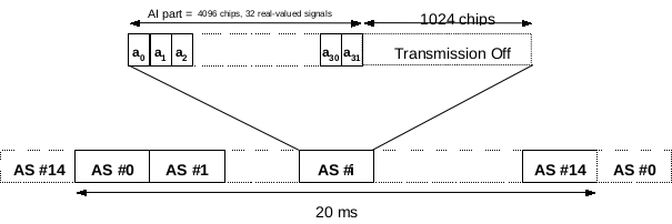
The AICH consists of a repeated sequence of 15 consecutive access slots (AS), each of length 5120 chips. Each access slot consists of two parts, an Acquisition-Indicator (AI) part consisting of 32 real-valued signals and a part of duration 1024 chips with no transmission that is not formally part of the AICH. The part of the slot with no transmission is reserved for possible future use by other physical channels.
PICH
Function:
The Paging Indicator Channel (PICH) is a fixed rate (SF=256) physical channel used to carry the paging indicators. The PICH is associated either with an S-CCPCH to which a PCH transport channel is mapped, or with a HS-SCCH associated with the HS-PDSCH(s) to which a HS-DSCH transport channel carrying paging messages is mapped.
Modulation:
Frame/Subframe Structure:
The following figure is Figure 24: Structure of Paging Indicator Channel (PICH) from TS 25.211-870 Physical channels and mapping of transport channels onto physical channels (FDD):
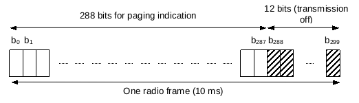
One PICH radio frame of length 10 ms consists of 300 bits (b0, b1, …, b299). Of these, 288 bits (b0, b1, …, b287) are used to carry paging indicators. The remaining 12 bits are not formally part of the PICH and shall not be transmitted (DTX). The part of the frame with no transmission is reserved for possible future use.
MICH
Function:
The MBMS Indicator Channel (MICH) is a fixed rate (SF=256) physical channel used to carry the MBMS notification indicators. The MICH is always associated with an S-CCPCH to which a FACH transport channel is mapped.
Modulation:
Frame/Subframe Structure:
The following figure is Figure 26D: Structure of MBMS Indicator Channel (MICH) from TS 25.211-870 Physical channels and mapping of transport channels onto physical channels (FDD):
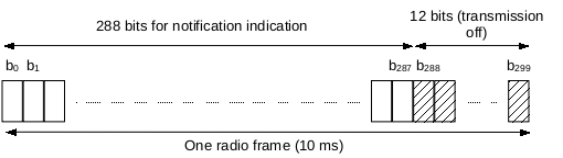
One MICH radio frame of length 10 ms consists of 300 bits (b0, b1, …, b299). Of these, 288 bits (b0, b1, …, b287) are used to carry notification indicators. The remaining 12 bits are not formally part of the MICH and shall not be transmitted (DTX).
PRACH
Function:
The Physical Random Access Channel (PRACH) is used to carry the RACH. The random-access transmission is based on a Slotted ALOHA approach with fast acquisition indication. The UE can start the random-access transmission at the beginning of a number of well-defined time intervals, denoted access slots.
Modulation:
Frame/Subframe Structure:
The following figure is Figure 3: RACH access slot numbers and their spacing from TS 25.211-870 Physical channels and mapping of transport channels onto physical channels (FDD):

The following figure is Figure 4: Structure of the random-access transmission from TS 25.211-870 Physical channels and mapping of transport channels onto physical channels (FDD):

The random-access transmission consists of one or several preambles of length 4096 chips and a message of length 10 ms or 20 ms. Each preamble is of length 4096 chips and consists of 256 repetitions of a signature of length 16 chips. There are a maximum of 16 available signatures.
The following figure is Figure 5: Structure of the random-access message part radio frame from TS 25.211-870 Physical channels and mapping of transport channels onto physical channels (FDD):

Each slot consists of two parts, a data part to which the RACH transport channel is mapped and a control part that carries Layer 1 control information. The data and control parts are transmitted in parallel. A 10 ms message part consists of one message part radio frame, while a 20 ms message part consists of two consecutive 10 ms message part radio frames.
The input sequence of PRACH comes from output of RACH, refer to General Channel Coding for TrCHs.
Configuration:
IE PRACH info in following messages:
- System Information Block type 5 and 5bis
- System Information Block type 6
CPICH
Function:
The Common Pilot Channel (CPICH) is a fixed rate (30 kbps, SF=256) downlink physical channel that carries a pre-defined bit sequence. There are two types of Common pilot channels, the Primary Common Pilot Channel (P-CPICH) and Secondary Common Pilot Channel (S-CPICH). They differ in their use and the limitations placed on their physical features.
P-CPICH:
- The same channelization code is always used for the P-CPICH;
- The P-CPICH is scrambled by the primary scrambling code;
- There is one and only one P-CPICH per cell;
- The P-CPICH is broadcast over the entire cell.
S-CPICH:
- An arbitrary channelization code of SF=256 is used for the S-CPICH;
- An S-CPICH is scrambled by either the primary or a secondary scrambling code;
- There may be zero, one, or several S-CPICH per cell;
- An S-CPICH may be transmitted over the entire cell or only over a part of the cell;
- An S-CPICH that is intended to be used as phase reference for the second transmit antenna by UEs configured in MIMO mode shall be transmitted over the entire cell using the primary scrambling code and the antenna 1 pattern.
Modulation:
Frame/Subframe Structure:
The following figure is Figure 13: Frame structure for Common Pilot Channel from TS 25.211-870 Physical channels and mapping of transport channels onto physical channels (FDD):

The following figure is Figure 14: Modulation pattern for Common Pilot Channel from TS 25.211-870 Physical channels and mapping of transport channels onto physical channels (FDD):
HS-PDSCH
Function:
The High Speed Physical Downlink Shared Channel (HS-PDSCH) is used to carry the High Speed Downlink Shared Channel (HS-DSCH). A HS-PDSCH corresponds to one channelization code of fixed spreading factor SF=16 from the set of channelization codes reserved for HS-DSCH transmission.
Modulation:
An HS-PDSCH may use QPSK, 16QAM or 64QAM modulation symbols.
Frame/Subframe Structure:
The following figure is Figure 26B: Subframe structure for the HS-PDSCH from TS 25.211-870 Physical channels and mapping of transport channels onto physical channels (FDD):

The input sequence of HS-PDSCH comes from output of Channel Coding for HS-DSCH.
HS-SCCH
Function:
The Shared Control Channel for HS-DSCH (HS-SCCH) is a fixed rate (60 kbps, SF=128) downlink physical channel used to carry downlink signalling related to HS-DSCH transmission.
Modulation:
Frame/Subframe Structure:
The following figure is Figure 26A: Subframe structure for the HS-SCCH from TS 25.211-870 Physical channels and mapping of transport channels onto physical channels (FDD):

The input sequence of HS-SCCH comes from output of Channel Coding for HS-SCCH.
HS-DPCCH
Function:
The Dedicated Physical Control Channel for HS-DSCH (HS-DPCCH) carries uplink feedback signalling related to downlink HS-DSCH transmission and to HS-SCCH orders. The feedback signalling consists of Hybrid-ARQ Acknowledgement (HARQ-ACK) and Channel-Quality Indication (CQI) and in case the UE is configured in MIMO mode of Precoding Control Indication (PCI) as well. There is at most one HS-DPCCH on each radio link. The HS-DPCCH can only exist together with an uplink DPCCH.
Modulation:
Frame/Subframe Structure:
The following figure is Figure 2A: Frame structure for uplink HS-DPCCH from TS 25.211-870 Physical channels and mapping of transport channels onto physical channels (FDD):
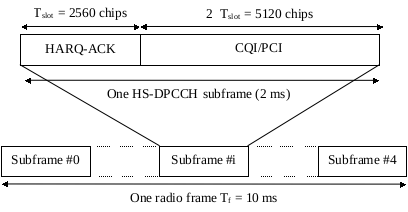
The spreading factor of the HS-DPCCH is SF=256 i.e. there are 10 bits per uplink HS-DPCCH slot.
The input sequence of HS-DPCCH comes from output of Channel Coding for HS-DPCCH.
DPDCH / DPCCH
-
DPDCH and DPCCH (uplink)
Function:
The uplink Dedicated Physical Data Channel (DPDCH) is used to carry the DCH transport channel. There may be zero, one, or several uplink DPDCHs on each radio link.
The uplink Dedicated Physical Control Channel (DPCCH) is used to carry control information generated at Layer 1. The Layer 1 control information consists of known pilot bits to support channel estimation for coherent detection, transmit power-control (TPC) commands, feedback information (FBI), and an optional transport-format combination indicator (TFCI). The transport-format combination indicator (TFCI) informs the receiver about the instantaneous transport format combination of the transport channels mapped to the simultaneously transmitted uplink DPDCH radio frame. There is one and only one uplink DPCCH on each radio link.
Modulation:
Frame/Subframe Structure:
The following figure is Figure 1: Frame structure for uplink DPDCH/DPCCH from TS 25.211-870 Physical channels and mapping of transport channels onto physical channels (FDD):
The DPDCH and DPCCH are always frame aligned with each other. The parameter k determines the number of bits per uplink DPDCH slot. It is related to the spreading factor SF of the DPDCH as SF = 256 / 2^k. The DPDCH spreading factor may range from 256 down to 4. The spreading factor of the uplink DPCCH is always equal to 256, i.e. there are 10 bits per uplink DPCCH slot.
The input sequence of DPDCH comes from output of DCH, refer to General Channel Coding for TrCHs.
Configuration:
IE Uplink DPCH info in the following messages:
- CELL UPDATE CONFIRM
- HANDOVER TO UTRAN COMMAND
- TRANSPORT CHANNEL RECONFIGURATION
- PHYSICAL CHANNEL RECONFIGURATION
- RADIO BEARER SETUP
- RADIO BEARER RECONFIGURATION
- RADIO BEARER RELEASE
- RRC CONNECTION SETUP
-
DPDCH and DPCCH (downlink)
Function:
Within one downlink DPCH, dedicated data generated at Layer 2 and above, i.e. the dedicated transport channel (DCH), is transmitted in time-multiplex with control information generated at Layer 1 (known pilot bits, TPC commands, and an optional TFCI). The downlink DPCH can thus be seen as a time multiplex of a downlink DPDCH and a downlink DPCCH.
Modulation:
Frame/Subframe Structure:
The following figure is Figure 9: Frame structure for downlink DPCH from TS 25.211-870 Physical channels and mapping of transport channels onto physical channels (FDD):

The input sequence of DPDCH comes from output of DCH, refer to General Channel Coding for TrCHs.
F-DPCH
Function:
The Fractional Dedicated Physical Channel (F-DPCH) carries control information generated at layer 1 (TPC commands). It is a special case of downlink DPCCH.
Modulation:
Frame/Subframe Structure:
The following figure is Figure 12B: Frame structure for F-DPCH from TS 25.211-870 Physical channels and mapping of transport channels onto physical channels (FDD):

E-DPDCH / E-DPCCH
Function:
The E-DCH Dedicated Physical Data Channel (E-DPDCH) is used to carry the E-DCH transport channel. There may be zero, one, or several E-DPDCH on each radio link.
The E-DPCCH is a physical channel used to transmit control information associated with the E-DCH. There is at most one E-DPCCH on each radio link. E-DPCCH shall not be transmitted in a slot unless DPCCH is also transmitted in the same slot.
Modulation:
An E-DPDCH may use BPSK or 4PAM modulation symbols.
Frame/Subframe Structure:
The following figure is Figure 2B: E-DPDCH frame structure from TS 25.211-870 Physical channels and mapping of transport channels onto physical channels (FDD):
The input sequence of E-DPCCH comes from output of Channel Coding for E-DCH.
The input sequence of E-DPCCH comes from output of Channel Coding for E-DPCCH.
Configuration:
IE E-DPDCH info in the following messages:
- System Information Block type 5 and 5bis
E-AGCH
Function:
The E-DCH Absolute Grant Channel (E-AGCH) is a fixed rate (30 kbps, SF=256) downlink physical channel carrying the uplink E-DCH absolute grant.
Modulation:
Frame/Subframe Structure:
The following figure is Figure 26C: Sub-frame structure for the E-AGCH from TS 25.211-870 Physical channels and mapping of transport channels onto physical channels (FDD):
The input sequence of E-AGCH comes from output of Channel Coding for E-AGCH.
E-RGCH / E-HICH
Function:
The E-DCH Relative Grant Channel (E-RGCH) is a fixed rate (SF=128) dedicated downlink physical channel carrying the uplink E-DCH relative grants.
The E-DCH Hybrid ARQ Indicator Channel (E-HICH) is a fixed rate (SF=128) dedicated downlink physical channel carrying the uplink E-DCH hybrid ARQ acknowledgement indicator.
Modulation:
Frame/Subframe Structure:
The following figure is Figure 12A: E-RGCH and E-HICH structure from TS 25.211-870 Physical channels and mapping of transport channels onto physical channels (FDD):
The input sequence of E-RGCH comes from output of Mapping for E-RGCH Relative Grant.
The input sequence of E-HICH comes from output of Mapping for E-HICH ACK/NACK.
Configuration:
IE E-RGCH Info in the following messages:
- CELL UPDATE CONFIRM
- HANDOVER TO UTRAN COMMAND
- TRANSPORT CHANNEL RECONFIGURATION
- PHYSICAL CHANNEL RECONFIGURATION
- RADIO BEARER SETUP
- RADIO BEARER RELEASE
- RRC CONNECTION SETUP
- ACTIVE SET UPDATE
IE E-HICH Info in the following messages:
- System Information Block type 5 and 5bis
Physical Channel Spreading/Modulation
Spreading is applied to the physical channels. It consists of two operations.
-
The first is the channelisation operation, which transforms every data symbol into a number of chips, thus increasing the bandwidth of the signal. The number of chips per data symbol is called the Spreading Factor (SF). With the channelisation, data symbols on so-called I- and Q-branches are independently multiplied with an Orthogonal Variable Spreading Factor (OVSF) code.
-
The second operation is the scrambling operation, where a scrambling code is applied to the spread signal. With the scrambling operation, the resultant signals of channelisation operation on the I- and Q-branches are further multiplied by complex-valued scrambling code, where I and Q denote real and imaginary parts, respectively.
Spreading and Modulation for Uplink Physical Channels
The spreading operation specified in the following figures includes a spreading stage, a weighting stage, and an IQ mapping stage. In the process, the streams of real-valued chips on the I and Q branches are summed; this results in a complex-valued stream of chips for each set of channels.
The following figure is Figure 1A: Spreading for uplink DPCCH/DPDCHs of TS 25.213-850 Spreading and modulation (FDD):
The following figure is Figure 1B: Spreading for uplink HS-DPCCH of TS 25.213-850 Spreading and modulation (FDD):
The following figure is Figure 1C: Spreading for E-DPDCH/E-DPCCH of TS 25.213-850 Spreading and modulation (FDD):
The following figure is Figure 1: Spreading for uplink dedicated channels of TS 25.213-850 Spreading and modulation (FDD):
The following figure is Figure 2: Spreading of PRACH message part of TS 25.213-850 Spreading and modulation (FDD):
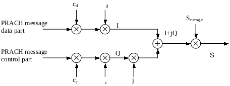
The following figure is Figure 7: Uplink modulation of TS 25.213-850 Spreading and modulation (FDD):
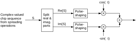
Spreading and Modulation for Downlink Physical Channels
The following figure is Figure 8: Spreading for all downlink physical channels except SCH of TS 25.213-850 Spreading and modulation (FDD):
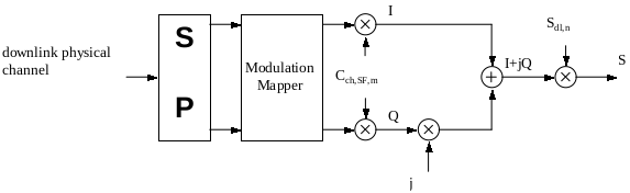
The following figure is Figure 9: Combining of downlink physical channels of TS 25.213-850 Spreading and modulation (FDD):
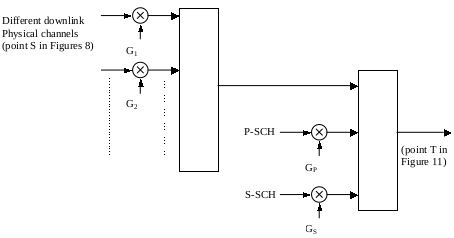
The following figure is Figure 11: Downlink modulation of TS 25.213-850 Spreading and modulation (FDD):

Timing relationship between physical channels
The P-CCPCH, on which the cell SFN is transmitted, is used as timing reference for all the physical channels, directly for downlink and indirectly for uplink.
The following figure is Figure 29: Radio frame timing and access slot timing of downlink physical channels from TS 25.211-870 Physical channels and mapping of transport channels onto physical channels (FDD):
The following figure is Figure 30: Timing relation between PICH frame and associated S-CCPCH frame from TS 25.211-870 Physical channels and mapping of transport channels onto physical channels (FDD):
The following figure is Figure 30a: Timing relation between PICH frame and associated HS-SCCH subframes from TS 25.211-870 Physical channels and mapping of transport channels onto physical channels (FDD):
The following figure is Figure 31: Timing relation between PRACH and AICH as seen at the UE from TS 25.211-870 Physical channels and mapping of transport channels onto physical channels (FDD):
The following figure is Figure 31A: UL/DL timing relation for Enhanced Uplink in CELL_FACH state and IDLE mode as seen at the UE from TS 25.211-870 Physical channels and mapping of transport channels onto physical channels (FDD):

The following figure is Figure 34: Timing structure at the UE for HS-DPCCH control signalling from TS 25.211-870 Physical channels and mapping of transport channels onto physical channels (FDD):
The following figure is Figure 35: Timing relation between the HS-SCCH and the associated HS-PDSCH from TS 25.211-870 Physical channels and mapping of transport channels onto physical channels (FDD):

The following figure is Figure 36: Timing relation between MICH frame and associated S-CCPCH frame from TS 25.211-870 Physical channels and mapping of transport channels onto physical channels (FDD):

The following figure is Figure 37: E-HICH timing from TS 25.211-870 Physical channels and mapping of transport channels onto physical channels (FDD):
The following figure is Figure 38: E-RGCH timing from TS 25.211-870 Physical channels and mapping of transport channels onto physical channels (FDD):
The following figure is Figure 39: E-AGCH timing from TS 25.211-870 Physical channels and mapping of transport channels onto physical channels (FDD):
Data Link Layer (L2)
The Data Link Layer (L2) is split into following sublayers:
- Medium Access Control (MAC)
- Radio Link Control (RLC)
- Packet Data Convergence Protocol (PDCP)
- Broadcast/Multicast Control (BMC)
Medium Access Control (MAC)
MAC Related Standards
The Medium Access Control (MAC) related standards include:
- TS 25.321 - Medium Access Control (MAC) protocol specification
MAC Services
According to section 5.3.1.1 MAC Services to upper layers of TS 25.301-870 Radio Interface Protocol Architecture:
The Medium Access Control (MAC) layer provides data transfer services on logical channels. Each logical channel type is defined by what type of information is transferred. The MAC layer offers following services to upper layers:
- Data transfer
- Reallocation of radio resources and MAC parameters
- Reporting of measurements
The Medium Access Control (MAC) defines following logical channels:
| Logical Channel | Control/Traffic | FDD/TDD | UL/DL | C-/U-plane |
|---|---|---|---|---|
| Broadcast Control Channel (BCCH) | Control | FDD/TDD | DL | C-plane |
| Paging Control Channel (PCCH) | Control | FDD/TDD | DL | C-plane |
| Common Control Channel (CCCH) | Control | FDD/TDD | UL/DL | C-plane |
| Dedicated Control Channel (DCCH) | Control | FDD/TDD | UL/DL | C-plane |
| Shared Channel Control Channel (SHCCH) | Control | TDD | UL/DL | C-plane |
| MBMS point-to-multipoint Control Channel (MCCH) | Control | FDD/TDD | DL | C-plane |
| MBMS point-to-multipoint Scheduling Channel (MSCH) | Control | FDD/TDD | DL | C-plane |
| Dedicated Traffic Channel (DTCH) | Traffic | FDD/TDD | UL/DL | U-plane |
| Common Traffic Channel (CTCH) | Traffic | FDD/TDD | UL/DL | U-plane |
| MBMS point-to-multipoint Traffic Channel (MTCH) | Traffic | FDD/TDD | DL | U-plane |
MAC Functions
According to section 5.3.1.2 MAC functions of TS 25.301-870 Radio Interface Protocol Architecture, the functions of MAC include:
- Mapping between logical channels and transport channels.
- Selection of appropriate Transport Format for each Transport Channel depending on instantaneous source rate.
- Priority handling between data flows of one UE.
- Priority handling between UEs by means of dynamic scheduling.
- Identification of UEs on common transport channels.
- Multiplexing/demultiplexing of upper layer PDUs into/from transport blocks delivered to/from the physical layer on common transport channels.
- Multiplexing/demultiplexing of upper layer PDUs into/from transport block sets delivered to/from the physical layer on dedicated transport channels.
- Multiplexing/demultiplexing of upper layer PDUs into transport blocks delivered to/from the physical layer on HS-DSCH.
- Traffic volume measurement.
- Transport Channel type switching.
- Ciphering.
- Access Service Class selection for RACH transmission and Enhanced Uplink for CELL_FACH and Idle mode.
- HARQ functionality for HS-DSCH and E-DCH transmission.
- Data segmentation/re-assembly for HS-DSCH and E-DCH.
- In-sequence delivery and assembly/disassembly of higher layer PDUs on HS-DSCH.
- In-sequence delivery and assembly/disassembly of higher layer PDUs on E-DCH.
Primitives between MAC and RRC/RLC
| Generic Name | Layers | Reference |
|---|---|---|
| CMAC-CONFIG-REQ | MAC - RRC | TS 25.321-8h0 S8.3.1 |
| CMAC-MEASUREMENT-REQ | MAC - RRC | TS 25.321-8h0 S8.3.1 |
| CMAC-MEASUREMENT-IND | MAC - RRC | TS 25.321-8h0 S8.3.1 |
| CMAC-STATUS-REQ | MAC - RRC | TS 25.321-8h0 S8.3.1 |
| CMAC-STATUS-IND | MAC - RRC | TS 25.321-8h0 S8.3.1 |
| MAC-DATA-REQ | MAC - RLC | TS 25.321-8h0 S8.2.1 |
| MAC-DATA-IND | MAC - RLC | TS 25.321-8h0 S8.2.1 |
| MAC-STATUS-IND | MAC - RLC | TS 25.321-8h0 S8.2.1 |
| MAC-STATUS-RESP | MAC - RLC | TS 25.321-8h0 S8.2.1 |
MAC peer-to-peer Communication
| Protocol Data Units | peer-to-peer | Reference |
|---|---|---|
| MAC PDU (not HS-DSCH or E-DCH) | MAC - MAC | TS 25.321-8h0 S9.1.2 |
| MAC-d PDU (HS-DSCH) | MAC - MAC | TS 25.321-8h0 S9.1.3 |
| MAC PDU (HS-DSCH) | MAC - MAC | TS 25.321-8h0 S9.1.4 |
| MAC PDU (E-DCH) | MAC - MAC | TS 25.321-8h0 S9.1.5 |
Logical Channels
According to TS 25.321-8g0 Medium Access Control (MAC) protocol specification, the following figure is Channel Mapping of 3GPP R8 FDD:
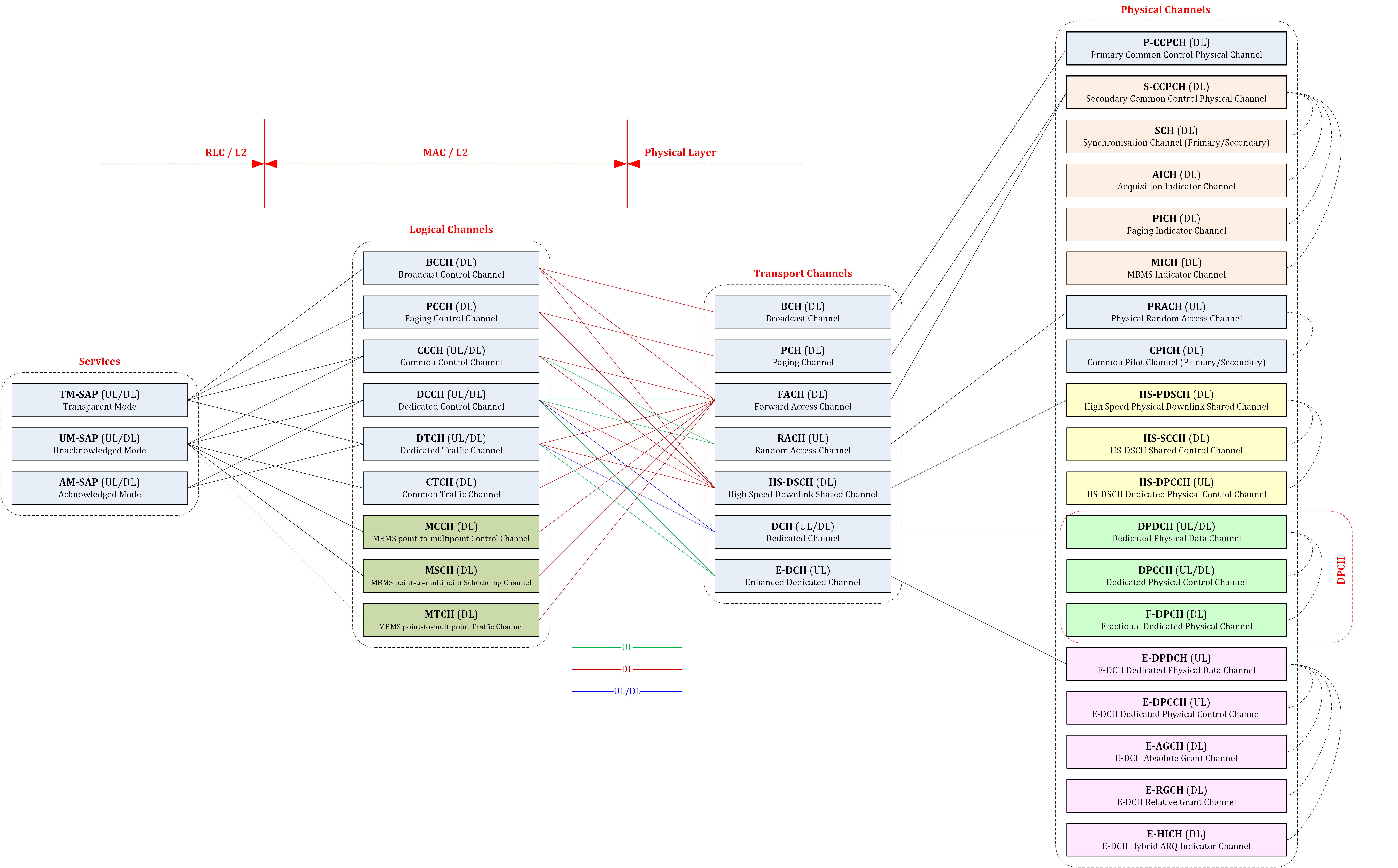
Refer to Transport Channels for Transport Channels.
Refer to Physical Channels for Physical Channels.
Radio Link Control (RLC)
RLC is divided into C-plane and U-plane.
RLC Related Standards
The Radio Link Control (RLC) related standards include:
- TS 25.322 - Radio Link Control (RLC) protocol specification
RLC Services
According to section 5.3.2.1 Services provided to the upper layer of TS 25.301-870 Radio Interface Protocol Architecture, the RLC layer provides the following services to the upper layer:
- Transparent data transfer
- Unacknowledged data transfer
- Acknowledged data transfer
- Maintenance of QoS as defined by upper layers
- Notification of unrecoverable errors
RLC Functions
According to section 5.3.2.2 RLC Functions of TS 25.301-870 Radio Interface Protocol Architecture, the RLC layer implements the following functions:
- Segmentation and reassembly.
- Concatenation.
- Padding.
- Transfer of user data.
- Error correction.
- In-sequence delivery of upper layer PDUs.
- Duplicate Detection.
- Flow control.
- Sequence number check.
- Protocol error detection and recovery.
- Ciphering.
- SDU discard.
Primitives between RLC and RRC/PDCP/BMC
| Generic Name | Layers | Reference |
|---|---|---|
| CRLC-CONFIG-REQ | RLC - RRC | TS 25.322-890 S8.1 |
| CRLC-SUSPEND-REQ | RLC - RRC | TS 25.322-890 S8.1 |
| CRLC-SUSPEND-CONF | RLC - RRC | TS 25.322-890 S8.1 |
| CRLC-RESUME-REQ | RLC - RRC | TS 25.322-890 S8.1 |
| CRLC-STATUS-IND | RLC - RRC | TS 25.322-890 S8.1 |
| RLC-AM-DATA-REQ | RLC - RRC/PDCP/BMC | TS 25.322-890 S8.1 |
| RLC-AM-DATA-IND | RLC - RRC/PDCP/BMC | TS 25.322-890 S8.1 |
| RLC-AM-DATA-CONF | RLC - RRC/PDCP/BMC | TS 25.322-890 S8.1 |
| RLC-UM-DATA-REQ | RLC - RRC/PDCP/BMC | TS 25.322-890 S8.1 |
| RLC-UM-DATA-IND | RLC - RRC/PDCP/BMC | TS 25.322-890 S8.1 |
| RLC-UM-DATA-CONF | RLC - RRC/PDCP/BMC | TS 25.322-890 S8.1 |
| RLC-TM-DATA-REQ | RLC - RRC/PDCP/BMC | TS 25.322-890 S8.1 |
| RLC-TM-DATA-IND | RLC - RRC/PDCP/BMC | TS 25.322-890 S8.1 |
| RLC-TM-DATA-CONF | RLC - RRC/PDCP/BMC | TS 25.322-890 S8.1 |
RLC peer-to-peer Communication
| Protocol Data Units | peer-to-peer | Reference |
|---|---|---|
| TMD PDU (Transparent Mode Data PDU) | RLC - RLC | TS 25.322-890 S9.1.1 |
| UMD PDU (Unacknowledged Mode Data PDU) | RLC - RLC | TS 25.322-890 S9.1.1 |
| AMD PDU (Acknowledged Mode Data PDU) | RLC - RLC | TS 25.322-890 S9.1.1 |
| STATUS PDU | RLC - RLC | TS 25.322-890 S9.1.2 |
| Piggybacked STATUS | RLC - RLC | TS 25.322-890 S9.1.2 |
| RESET PDU | RLC - RLC | TS 25.322-890 S9.1.2 |
| RESET ACK PDU | RLC - RLC | TS 25.322-890 S9.1.2 |
Packet Data Convergence Protocol (PDCP)
PDCP exists in the U-plane only.
PDCP Related Standards
The Packet Data Convergence Protocol (PDCP) related standards include:
- TS 25.323 - Packet Data Convergence Protocol (PDCP) specification
PDCP Services
According to section 5.3.3.1 PDCP Services provided to upper layers of TS 25.301-870 Radio Interface Protocol Architecture, the PDCP layer provides the following services to upper layers:
- PDCP SDU delivery
- CS counter delivery to JBM (Jitter Buffer Management)
PDCP Functions
According to section 5.3.3.2 PDCP Functions of TS 25.301-870 Radio Interface Protocol Architecture, the PDCP layer implements the following functions:
- Header compression and decompression.
- Transfer of user data.
- Support for lossless SRNS relocation or lossless DL RLC PDU size change.
- CS counter.
Primitives between PDCP and RRC/U-plane
| Generic Name | Layers | Reference |
|---|---|---|
| CPDCP-CONFIG-REQ | PDCP - RRC | TS 25.323-850 S7.1 |
| CPDCP-RELEASE-REQ | PDCP - RRC | TS 25.323-850 S7.1 |
| CPDCP-SN-REQ | PDCP - RRC | TS 25.323-850 S7.1 |
| CPDCP-RELOC-REQ | PDCP - RRC | TS 25.323-850 S7.1 |
| CPDCP-RELOC-CONF | PDCP - RRC | TS 25.323-850 S7.1 |
| CPDCP-CONTEXT-REQ | PDCP - RRC | TS 25.323-850 S7.1 |
| CPDCP-CONTEXT-CONF | PDCP - RRC | TS 25.323-850 S7.1 |
| PDCP-DATA-REQ | PDCP - U-plane | TS 25.323-850 S7.1 |
| PDCP-DATA-IND | PDCP - U-plane | TS 25.323-850 S7.1 |
PDCP peer-to-peer Communication
| Protocol Data Units | peer-to-peer | Reference |
|---|---|---|
| PDCP-No-Header PDU | PDCP - PDCP | TS 25.323-850 S8.2.1 |
| PDCP Data PDU | PDCP - PDCP | TS 25.323-850 S8.2.2 |
| PDCP SeqNum PDU | PDCP - PDCP | TS 25.323-850 S8.2.3 |
| PDCP AMR Data PDU | PDCP - PDCP | TS 25.323-850 S8.2.4 |
Broadcast/Multicast Control (BMC)
BMC exists in the U-plane only.
BMC Related Standards
The Broadcast/Multicast Control (BMC) related standards include:
- TS 25.324 - Broadcast/Multicast Control (BMC)
BMC Services
According to section 5.3.4.1 BMC Services of TS 25.301-870 Radio Interface Protocol Architecture:
The BMC-SAP provides a broadcast/multicast transmission service in the user plane on the radio interface for common user data in unacknowledged mode.
BMC Functions
According to section 5.3.4.2 BMC Functions of TS 25.301-870 Radio Interface Protocol Architecture, the BMC layer implements the following functions:
- Storage of Cell Broadcast Messages.
- Traffic volume monitoring and radio resource request for CBS.
- Scheduling of BMC messages.
- Transmission of BMC messages to UE.
- Delivery of Cell Broadcast messages to upper layer (NAS).
Primitives between BMC and RRC/U-plane
| Generic Name | Layers | Reference |
|---|---|---|
| CBMC-Measurement-IND | BMC - RRC | TS 25.324-800 S8.1.1.1 |
| CBMC-Rx-IND | BMC - RRC | TS 25.324-800 S8.1.1.2 |
| CBMC-Config-REQ | BMC - RRC | TS 25.324-800 S8.1.1.3 |
| BMC-Data-REQ | BMC - U-plane | TS 25.324-800 S8.2.1.1.1 |
| BMC-Data-IND | BMC - U-plane | TS 25.324-800 S8.2.1.1.2 |
| BMC-Data-CNF | BMC - U-plane | TS 25.324-800 S8.2.1.1.3 |
| BMC-Congestion-IND | BMC - U-plane | TS 25.324-800 S8.2.1.1.4 |
| BMC-Normal-IND | BMC - U-plane | TS 25.324-800 S8.2.1.1.5 |
| BMC-Activation-REQ | BMC - U-plane | TS 25.324-800 S8.2.1.1.6 |
| BMC-Deactivation-REQ | BMC - U-plane | TS 25.324-800 S8.2.1.1.7 |
| BMC-DRX-REQ | BMC - U-plane | TS 25.324-800 S8.2.1.1.8 |
| BMC-Error-IND | BMC - U-plane | TS 25.324-800 S8.2.1.1.9 |
| BMC-Data41-REQ | BMC - U-plane | TS 25.324-800 S8.2.1.2.1 |
| BMC-Data41-IND | BMC - U-plane | TS 25.324-800 S8.2.1.2.2 |
| BMC-Error41-IND | BMC - U-plane | TS 25.324-800 S8.2.1.2.2 |
BMC peer-to-peer Communication
| Protocol Data Units | peer-to-peer | Reference |
|---|---|---|
| BMC CBS Message | BMC - BMC | TS 25.324-800 S10.2 |
| BMC Schedule Message | BMC - BMC | TS 25.324-800 S10.3 |
| BMC CBS41 Message | BMC - BMC | TS 25.324-800 S10.4 |
Data flows through L2
According to section 5.3.5 Data flows through Layer 2 of TS 25.301-870 Radio Interface Protocol Architecture:
Data flows through layer 2 are characterised by the applied data transfer modes on RLC (acknowledged, unacknowledged and transparent transmission) in combination with the data transfer type on MAC, i.e. whether or not a MAC header is required. The case where no MAC header is required is referred to as transparent MAC transmission. Acknowledged and unacknowledged RLC transmissions both require a RLC header. In unacknowledged transmission, only one type of unacknowledged data PDU is exchanged between peer RLC entities. In acknowledged transmission, both (acknowledged) data PDUs and control PDUs are exchanged between peer RLC entities.
The following figure is Figure 6: Data flow for transparent RLC and MAC from TS 25.301-870 Radio Interface Protocol Architecture:
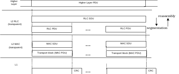
The following figure is Figure 7: Data flow for transparent RLC and non-transparent MAC from TS 25.301-870 Radio Interface Protocol Architecture:
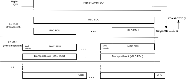
The following figure is Figure 8: Data flow for non-transparent RLC and transparent MAC from TS 25.301-870 Radio Interface Protocol Architecture:
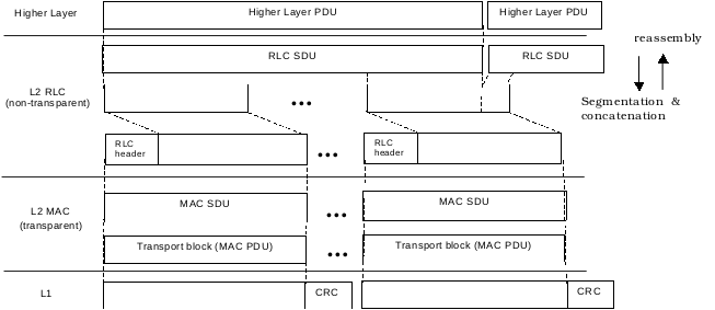
The following figure is Figure 9: Data flow for non-transparent RLC and MAC from TS 25.301-870 Radio Interface Protocol Architecture:
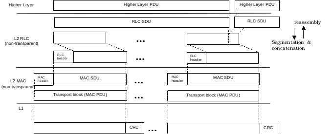
Network Layer (L3)
L3 is divided into C-plane and U-plane.
L3 Related Standards
The Network Layer (L3) related standards include:
- TS 24.007 - Mobile radio interface signalling layer 3; General aspects
- TS 25.331 - Radio Resource Control (RRC); Protocol specification
L3 Services
According to section 5.4.1 Uu Stratum services of TS 25.301-870 Radio Interface Protocol Architecture, the network layer (L3) provides the following services to upper layer:
- General Control (GC)
- Notification (Nt)
- Dedicated Control (DC)
L3 Functions
According to section 5.4.2 RRC functions of TS 25.301-870 Radio Interface Protocol Architecture, the Radio Resource Control (RRC) layer handles the control plane signalling of Layer 3 between the UEs and UTRAN. The RRC performs the following functions:
- Broadcast of information provided by the non-access stratum (Core Network).
- Broadcast of information related to the access stratum.
- Establishment, re-establishment, maintenance and release of an RRC connection between the UE and UTRAN.
- Establishment, reconfiguration and release of Radio Bearers.
- Assignment, reconfiguration and release of radio resources for the RRC connection.
- RRC connection mobility functions.
- Paging/notification.
- Routing of higher layer PDUs.
- Control of requested QoS.
- UE measurement reporting and control of the reporting.
- Outer loop power control.
- Control of ciphering.
- Slow DCA.
- Arbitration of radio resources on uplink DCH.
- Initial cell selection and re-selection in idle mode.
- Integrity protection.
- Initial Configuration for CBS.
- Allocation of radio resources for CBS.
- Configuration for CBS discontinuous reception.
- Timing advance control.
- MBMS control.
Primitives between RRC and PHY/MAC/RLC/PDCP/BMC/U-plane
The primitives between RRC and PHY/MAC/RLC/PDCP/BMC are described in following sections:
- Primitives between L1 and RRC/MAC
- Primitives between MAC and RRC/RLC
- Primitives between RLC and RRC/PDCP/BMC
- Primitives between PDCP and RRC/U-plane
- Primitives between BMC and RRC/U-plane
The primitives between RRC and the upper layers are described in section 6 Services provided by signalling layer 3 at the MS side of TS 24.007 - Mobile radio interface signalling layer 3; General aspects:
| Generic Name | Layers | Side | Reference |
|---|---|---|---|
| MMR_REG_REQ | RRC - C-plane | MS | TS 24.007-820 S6.1.2.1 |
| MMR_REG_CNF | RRC - C-plane | MS | TS 24.007-820 S6.1.2.2 |
| MMR_NREG_REQ | RRC - C-plane | MS | TS 24.007-820 S6.1.2.4 |
| MMR_NREG_IND | RRC - C-plane | MS | TS 24.007-820 S6.1.2.5 |
| MMR_CTS_ATTACH_REQ | RRC - C-plane | MS | TS 24.007-820 S6.1.3.1 |
| MMR_CTS_ATTACH_CNF | RRC - C-plane | MS | TS 24.007-820 S6.1.3.2 |
| MMR_CTS_ATTACH_REJ | RRC - C-plane | MS | TS 24.007-820 S6.1.3.3 |
| MMR_CTS_DETACH_IND | RRC - C-plane | MS | TS 24.007-820 S6.1.3.4 |
| MMR_CTS_ENROLL_REQ | RRC - C-plane | MS | TS 24.007-820 S6.1.3.5 |
| MMR_CTS_ENROLL_CNF | RRC - C-plane | MS | TS 24.007-820 S6.1.3.6 |
| MMR_CTS_ENROLL_REJ | RRC - C-plane | MS | TS 24.007-820 S6.1.3.7 |
| MMR_CTS_DE_ENROLL_IND | RRC - C-plane | MS | TS 24.007-820 S6.1.3.8 |
| MNCC_SETUP_REQ | RRC - C-plane | MS | TS 24.007-820 S6.2.2.1 |
| MNCC_SETUP_IND | RRC - C-plane | MS | TS 24.007-820 S6.2.2.2 |
| MNCC_SETUP_RSP | RRC - C-plane | MS | TS 24.007-820 S6.2.2.3 |
| MNCC_SETUP_CNF | RRC - C-plane | MS | TS 24.007-820 S6.2.2.4 |
| MNCC_SETUP_COMPLETE_REQ | RRC - C-plane | MS | TS 24.007-820 S6.2.2.5 |
| MNCC_SETUP_COMPLETE_IND | RRC - C-plane | MS | TS 24.007-820 S6.2.2.6 |
| MNCC_REJ_REQ | RRC - C-plane | MS | TS 24.007-820 S6.2.2.7 |
| MNCC_REJ_IND | RRC - C-plane | MS | TS 24.007-820 S6.2.2.8 |
| MNCC_CALL_CONF_REQ | RRC - C-plane | MS | TS 24.007-820 S6.2.2.9 |
| MNCC_CALL PROC_IND | RRC - C-plane | MS | TS 24.007-820 S6.2.2.10 |
| MNCC_PROGRESS_IND | RRC - C-plane | MS | TS 24.007-820 S6.2.2.11 |
| MNCC_ALERT_REQ | RRC - C-plane | MS | TS 24.007-820 S6.2.2.12 |
| MNCC_ALERT_IND | RRC - C-plane | MS | TS 24.007-820 S6.2.2.13 |
| MNCC_NOTIFY_REQ | RRC - C-plane | MS | TS 24.007-820 S6.2.2.14 |
| MNCC_NOTIFY_IND | RRC - C-plane | MS | TS 24.007-820 S6.2.2.15 |
| MNCC_DISC_REQ | RRC - C-plane | MS | TS 24.007-820 S6.2.2.16 |
| MNCC_DISC_IND | RRC - C-plane | MS | TS 24.007-820 S6.2.2.17 |
| MNCC_REL_REQ | RRC - C-plane | MS | TS 24.007-820 S6.2.2.18 |
| MNCC_REL_IND | RRC - C-plane | MS | TS 24.007-820 S6.2.2.19 |
| MNCC_REL_CNF | RRC - C-plane | MS | TS 24.007-820 S6.2.2.20 |
| MNCC_FACILITY_REQ | RRC - C-plane | MS | TS 24.007-820 S6.2.2.21 |
| MNCC_FACILITY_IND | RRC - C-plane | MS | TS 24.007-820 S6.2.2.22 |
| MNCC_START_DTMF_REQ | RRC - C-plane | MS | TS 24.007-820 S6.2.2.23 |
| MNCC_START_DTMF_CNF | RRC - C-plane | MS | TS 24.007-820 S6.2.2.24 |
| MNCC_STOP_DTMF_REQ | RRC - C-plane | MS | TS 24.007-820 S6.2.2.25 |
| MNCC_STOP_DTMF_CNF | RRC - C-plane | MS | TS 24.007-820 S6.2.2.26 |
| MNCC_MODIFY_REQ | RRC - C-plane | MS | TS 24.007-820 S6.2.2.27 |
| MNCC_MODIFY_IND | RRC - C-plane | MS | TS 24.007-820 S6.2.2.28 |
| MNCC_MODIFY_RES | RRC - C-plane | MS | TS 24.007-820 S6.2.2.29 |
| MNCC_MODIFY_CNF | RRC - C-plane | MS | TS 24.007-820 S6.2.2.30 |
| MNCC_SYNC_IND | RRC - C-plane | MS | TS 24.007-820 S6.2.2.31 |
| MNSS_BEGIN_REQ | RRC - C-plane | MS | TS 24.007-820 S6.3.2.1 |
| MNSS_BEGIN_IND | RRC - C-plane | MS | TS 24.007-820 S6.3.2.2 |
| MNSS_FACILITY_REQ | RRC - C-plane | MS | TS 24.007-820 S6.3.2.3 |
| MNSS_FACILITY_IND | RRC - C-plane | MS | TS 24.007-820 S6.3.2.4 |
| MNSS_END_REQ | RRC - C-plane | MS | TS 24.007-820 S6.3.2.5 |
| MNSS_END_IND | RRC - C-plane | MS | TS 24.007-820 S6.3.2.6 |
| SMREG-PDP-ACTIVATE-REQ | RRC - C-plane | MS | TS 24.007-820 S6.5.1.1 |
| SMREG-PDP-ACTIVATE-CNF | RRC - C-plane | MS | TS 24.007-820 S6.5.1.2 |
| SMREG-PDP-ACTIVATE-REJ | RRC - C-plane | MS | TS 24.007-820 S6.5.1.3 |
| SMREG-PDP-ACTIVATE-IND | RRC - C-plane | MS | TS 24.007-820 S6.5.1.4 |
| SMREG-PDP-ACTIVATE-REJ-RSP | RRC - C-plane | MS | TS 24.007-820 S6.5.1.14 |
| SMREG-PDP-DEACTIVATE-REQ | RRC - C-plane | MS | TS 24.007-820 S6.5.1.5 |
| SMREG-PDP-DEACTIVATE-CNF | RRC - C-plane | MS | TS 24.007-820 S6.5.1.6 |
| SMREG-PDP-DEACTIVATE-IND | RRC - C-plane | MS | TS 24.007-820 S6.5.1.7 |
| SMREG-PDP-ACTIVATE-SEC-REQ | RRC - C-plane | MS | TS 24.007-820 S6.5.1.15 |
| SMREG-PDP-ACTIVATE-SEC-CNF | RRC - C-plane | MS | TS 24.007-820 S6.5.1.16 |
| SMREG-PDP-ACTIVATE-SEC-REJ | RRC - C-plane | MS | TS 24.007-820 S6.5.1.17 |
| SMREG-PDP-MODIFY-REQ | RRC - C-plane | MS | TS 24.007-820 S6.5.1.18 |
| SMREG-PDP-MODIFY-CNF | RRC - C-plane | MS | TS 24.007-820 S6.5.1.19 |
| SMREG-PDP-MODIFY-REJ | RRC - C-plane | MS | TS 24.007-820 S6.5.1.20 |
| SMREG-PDP-MODIFY-IND | RRC - C-plane | MS | TS 24.007-820 S6.5.1.8 |
| SMREG-MBMS-ACTIVATE-REQ | RRC - C-plane | MS | TS 24.007-820 S6.5.1.21 |
| SMREG-MBMS-ACTIVATE-CNF | RRC - C-plane | MS | TS 24.007-820 S6.5.1.22 |
| SMREG-MBMS-ACTIVATE-REJ | RRC - C-plane | MS | TS 24.007-820 S6.5.1.23 |
| SMREG-MBMS-ACTIVATE-IND | RRC - C-plane | MS | TS 24.007-820 S6.5.1.25 |
| SMREG-MBMS-ACTIVATE-REJ-RSP | RRC - C-plane | MS | TS 24.007-820 S6.5.1.24 |
| RABMSM-ACTIVATE-IND | RRC - C-plane | MS | TS 24.007-820 S6.5.3.1 |
| RABMSM-ACTIVATE-RSP | RRC - C-plane | MS | TS 24.007-820 S6.5.3.2 |
| RABMSM-DEACTIVATE-IND | RRC - C-plane | MS | TS 24.007-820 S6.5.3.3 |
| RABMSM-DEACTIVATE-RSP | RRC - C-plane | MS | TS 24.007-820 S6.5.3.4 |
| RABMSM-DEACTIVATE-REQ | RRC - C-plane | MS | TS 24.007-820 S6.5.3.5 |
| RABMSM-MODIFY-IND | RRC - C-plane | MS | TS 24.007-820 S6.5.3.6 |
| RABMSM-MODIFY-RSP | RRC - C-plane | MS | TS 24.007-820 S6.5.3.7 |
| RABMSM-STATUS-REQ | RRC - C-plane | MS | TS 24.007-820 S6.5.3.8 |
| GMMREG-ATTACH-REQ | RRC - C-plane | MS | TS 24.007-820 S6.6.1.1 |
| GMMREG-ATTACH-CNF | RRC - C-plane | MS | TS 24.007-820 S6.6.1.2 |
| GMMREG-ATTACH-REJ | RRC - C-plane | MS | TS 24.007-820 S6.6.1.3 |
| GMMREG-DETACH-REQ | RRC - C-plane | MS | TS 24.007-820 S6.6.1.4 |
| GMMREG-DETACH-CNF | RRC - C-plane | MS | TS 24.007-820 S6.6.1.5 |
| GMMREG-DETACH-IND | RRC - C-plane | MS | TS 24.007-820 S6.6.1.6 |
| LL-ESTABLISH-REQ | RRC - C-plane | MS | TS 24.007-820 S6.7.2.1 |
| LL-ESTABLISH-CNF | RRC - C-plane | MS | TS 24.007-820 S6.7.2.2 |
| LL-ESTABLISH-IND | RRC - C-plane | MS | TS 24.007-820 S6.7.2.3 |
| LL-ESTABLISH-RSP | RRC - C-plane | MS | TS 24.007-820 S6.7.2.4 |
| LL-RELEASE-REQ | RRC - C-plane | MS | TS 24.007-820 S6.7.2.5 |
| LL-RELEASE-CFN | RRC - C-plane | MS | TS 24.007-820 S6.7.2.6 |
| LL-RELEASE-IND | RRC - C-plane | MS | TS 24.007-820 S6.7.2.7 |
| LL-XID-REQ | RRC - C-plane | MS | TS 24.007-820 S6.7.2.8 |
| LL-XID-IND | RRC - C-plane | MS | TS 24.007-820 S6.7.2.9 |
| LL-XID-RSP | RRC - C-plane | MS | TS 24.007-820 S6.7.2.10 |
| LL-XID-CNF | RRC - C-plane | MS | TS 24.007-820 S6.7.2.11 |
| LL-DATA-REQ | RRC - C-plane | MS | TS 24.007-820 S6.7.2.12 |
| LL-DATA-CNF | RRC - C-plane | MS | TS 24.007-820 S6.7.2.13 |
| LL-DATA-IND | RRC - C-plane | MS | TS 24.007-820 S6.7.2.14 |
| LL-UNITDATA-REQ | RRC - C-plane | MS | TS 24.007-820 S6.7.2.15 |
| LL-UNITDATA-IND | RRC - C-plane | MS | TS 24.007-820 S6.7.2.16 |
| LL-STATUS-IND | RRC - C-plane | MS | TS 24.007-820 S6.7.2.17 |
| MNLCS_BEGIN_REQ | RRC - C-plane | MS | TS 24.007-820 S6.8.2.1 |
| MNLCS_BEGIN_IND | RRC - C-plane | MS | TS 24.007-820 S6.8.2.2 |
| MNLCS_FACILITY_REQ | RRC - C-plane | MS | TS 24.007-820 S6.8.2.3 |
| MNLCS_FACILITY_IND | RRC - C-plane | MS | TS 24.007-820 S6.8.2.4 |
| MNLCS_END_REQ | RRC - C-plane | MS | TS 24.007-820 S6.8.2.5 |
| MNLCS_END_IND | RRC - C-plane | MS | TS 24.007-820 S6.8.2.6 |
RRC peer-to-peer Communication
| Protocol Data Units | peer-to-peer | Reference |
|---|---|---|
| ACTIVE SET UPDATE | RRC - RRC | TS 25.331-8n0 S10.2.1 |
| ACTIVE SET UPDATE COMPLETE | RRC - RRC | TS 25.331-8n0 S10.2.2 |
| ACTIVE SET UPDATE FAILURE | RRC - RRC | TS 25.331-8n0 S10.2.3 |
| ASSISTANCE DATA DELIVERY | RRC - RRC | TS 25.331-8n0 S10.2.4 |
| CELL CHANGE ORDER FROM UTRAN | RRC - RRC | TS 25.331-8n0 S10.2.5 |
| CELL CHANGE ORDER FROM UTRAN FAILURE | RRC - RRC | TS 25.331-8n0 S10.2.6 |
| CELL UPDATE | RRC - RRC | TS 25.331-8n0 S10.2.7 |
| CELL UPDATE CONFIRM | RRC - RRC | TS 25.331-8n0 S10.2.8 |
| COUNTER CHECK | RRC - RRC | TS 25.331-8n0 S10.2.9 |
| DOWNLINK DIRECT TRANSFER | RRC - RRC | TS 25.331-8n0 S10.2.10 |
| ETWS PRIMARY NOTIFICATION WITH SECURITY | RRC - RRC | TS 25.331-8n0 S10.2.12a |
| HANDOVER FROM UTRAN COMMAND | RRC - RRC | TS 25.331-8n0 S10.2.15 |
| HANDOVER FROM UTRAN FAILURE | RRC - RRC | TS 25.331-8n0 S10.2.16 |
| HANDOVER TO UTRAN COMMAND | RRC - RRC | TS 25.331-8n0 S10.2.16a |
| HANDOVER TO UTRAN COMPLETE | RRC - RRC | TS 25.331-8n0 S10.2.16b |
| INITIAL DIRECT TRANSFER | RRC - RRC | TS 25.331-8n0 S10.2.16c |
| INTER RAT HANDOVER INFO | RRC - RRC | TS 25.331-8n0 S10.2.16d |
| MBMS ACCESS INFORMATION | RRC - RRC | TS 25.331-8n0 S10.2.16e |
| MBMS COMMON P-T-M RB INFORMATION | RRC - RRC | TS 25.331-8n0 S10.2.16f |
| MBMS CURRENT CELL P-T-M RB INFORMATION | RRC - RRC | TS 25.331-8n0 S10.2.16g |
| MBMS GENERAL INFORMATION | RRC - RRC | TS 25.331-8n0 S10.2.16h |
| MBMS MODIFICATION REQUEST | RRC - RRC | TS 25.331-8n0 S10.2.16i |
| MBMS MODIFIED SERVICES INFORMATION | RRC - RRC | TS 25.331-8n0 S10.2.16j |
| MBMS NEIGHBOURING CELL P-T-M RB INFORMATION | RRC - RRC | TS 25.331-8n0 S10.2.16k |
| MBMS SCHEDULING INFORMATION | RRC - RRC | TS 25.331-8n0 S10.2.16L |
| MBMS UNMODIFIED SERVICES INFORMATION | RRC - RRC | TS 25.331-8n0 S10.2.16m |
| MEASUREMENT CONTROL | RRC - RRC | TS 25.331-8n0 S10.2.17 |
| MEASUREMENT CONTROL FAILURE | RRC - RRC | TS 25.331-8n0 S10.2.18 |
| MEASUREMENT REPORT | RRC - RRC | TS 25.331-8n0 S10.2.19 |
| PAGING TYPE 1 | RRC - RRC | TS 25.331-8n0 S10.2.20 |
| PAGING TYPE 2 | RRC - RRC | TS 25.331-8n0 S10.2.21 |
| PHYSICAL CHANNEL RECONFIGURATION | RRC - RRC | TS 25.331-8n0 S10.2.22 |
| PHYSICAL CHANNEL RECONFIGURATION COMPLETE | RRC - RRC | TS 25.331-8n0 S10.2.23 |
| PHYSICAL CHANNEL RECONFIGURATION FAILURE | RRC - RRC | TS 25.331-8n0 S10.2.24 |
| PHYSICAL SHARED CHANNEL ALLOCATION | RRC - RRC | TS 25.331-8n0 S10.2.25 |
| PUSCH CAPACITY REQUEST | RRC - RRC | TS 25.331-8n0 S10.2.26 |
| RADIO BEARER RECONFIGURATION | RRC - RRC | TS 25.331-8n0 S10.2.27 |
| RADIO BEARER RECONFIGURATION COMPLETE | RRC - RRC | TS 25.331-8n0 S10.2.28 |
| RADIO BEARER RECONFIGURATION FAILURE | RRC - RRC | TS 25.331-8n0 S10.2.29 |
| RADIO BEARER RELEASE | RRC - RRC | TS 25.331-8n0 S10.2.30 |
| RADIO BEARER RELEASE COMPLETE | RRC - RRC | TS 25.331-8n0 S10.2.31 |
| RADIO BEARER RELEASE FAILURE | RRC - RRC | TS 25.331-8n0 S10.2.32 |
| RADIO BEARER SETUP | RRC - RRC | TS 25.331-8n0 S10.2.33 |
| RADIO BEARER SETUP COMPLETE | RRC - RRC | TS 25.331-8n0 S10.2.34 |
| RADIO BEARER SETUP FAILURE | RRC - RRC | TS 25.331-8n0 S10.2.35 |
| RRC CONNECTION REJECT | RRC - RRC | TS 25.331-8n0 S10.2.36 |
| RRC CONNECTION RELEASE | RRC - RRC | TS 25.331-8n0 S10.2.37 |
| RRC CONNECTION RELEASE COMPLETE | RRC - RRC | TS 25.331-8n0 S10.2.38 |
| RRC CONNECTION REQUEST | RRC - RRC | TS 25.331-8n0 S10.2.39 |
| RRC CONNECTION SETUP | RRC - RRC | TS 25.331-8n0 S10.2.40 |
| RRC CONNECTION SETUP COMPLETE | RRC - RRC | TS 25.331-8n0 S10.2.41 |
| RRC FAILURE INFO | RRC - RRC | TS 25.331-8n0 S10.2.41a |
| RRC STATUS | RRC - RRC | TS 25.331-8n0 S10.2.42 |
| SECURITY MODE COMMAND | RRC - RRC | TS 25.331-8n0 S10.2.43 |
| SECURITY MODE COMPLETE | RRC - RRC | TS 25.331-8n0 S10.2.44 |
| SECURITY MODE FAILURE | RRC - RRC | TS 25.331-8n0 S10.2.45 |
| SIGNALLING CONNECTION RELEASE | RRC - RRC | TS 25.331-8n0 S10.2.46 |
| SIGNALLING CONNECTION RELEASE INDICATION | RRC - RRC | TS 25.331-8n0 S10.2.47 |
| SYSTEM INFORMATION | RRC - RRC | TS 25.331-8n0 S10.2.48 |
| SYSTEM INFORMATION CHANGE INDICATION | RRC - RRC | TS 25.331-8n0 S10.2.49 |
| TRANSPORT CHANNEL RECONFIGURATION | RRC - RRC | TS 25.331-8n0 S10.2.50 |
| TRANSPORT CHANNEL RECONFIGURATION COMPLETE | RRC - RRC | TS 25.331-8n0 S10.2.51 |
| TRANSPORT CHANNEL RECONFIGURATION FAILURE | RRC - RRC | TS 25.331-8n0 S10.2.52 |
| TRANSPORT FORMAT COMBINATION CONTROL | RRC - RRC | TS 25.331-8n0 S10.2.53 |
| TRANSPORT FORMAT COMBINATION CONTROL FAILURE | RRC - RRC | TS 25.331-8n0 S10.2.54 |
| UE CAPABILITY ENQUIRY | RRC - RRC | TS 25.331-8n0 S10.2.55 |
| UE CAPABILITY INFORMATION | RRC - RRC | TS 25.331-8n0 S10.2.56 |
| UE CAPABILITY INFORMATION CONFIRM | RRC - RRC | TS 25.331-8n0 S10.2.57 |
| UPLINK DIRECT TRANSFER | RRC - RRC | TS 25.331-8n0 S10.2.58 |
| UPLINK PHYSICAL CHANNEL CONTROL | RRC - RRC | TS 25.331-8n0 S10.2.59 |
| URA UPDATE | RRC - RRC | TS 25.331-8n0 S10.2.60 |
| URA UPDATE CONFIRM | RRC - RRC | TS 25.331-8n0 S10.2.61 |
| UTRAN MOBILITY INFORMATION | RRC - RRC | TS 25.331-8n0 S10.2.62 |
| UTRAN MOBILITY INFORMATION CONFIRM | RRC - RRC | TS 25.331-8n0 S10.2.63 |
| UTRAN MOBILITY INFORMATION FAILURE | RRC - RRC | TS 25.331-8n0 S10.2.64 |
RRC Layer Model
The following figure is Figure 4.1-1: Mapping of UE state to 3GPP Specifications from TS 25.331-8n0 Radio Resource Control (RRC) protocol specification:
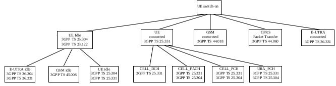
The following figure is Figure 4.2-1: UE side model of RRC from TS 25.331-8n0 Radio Resource Control (RRC) protocol specification:
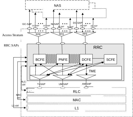
The following figure is Figure 4.2-2: UTRAN side RRC model (DS-MAP system) from TS 25.331-8n0 Radio Resource Control (RRC) protocol specification:
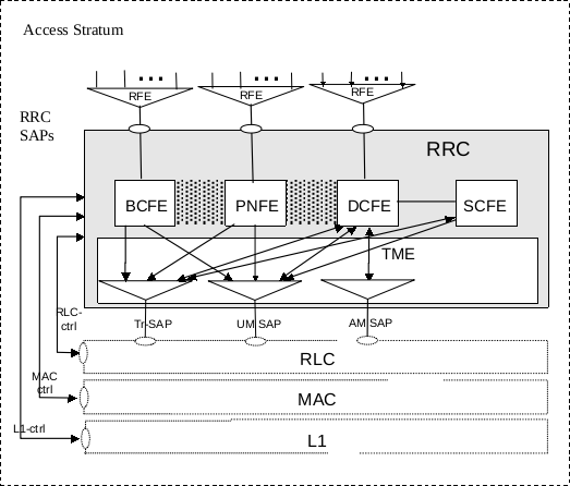
The following figure is Figure 4.2-3: UTRAN side RRC model (DS-41 System) from TS 25.331-8n0 Radio Resource Control (RRC) protocol specification:
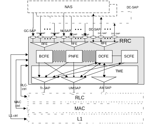
RRC States
The following figure is Figure 7.1-1: RRC States and State Transitions including GSM and E-UTRA from TS 25.331-8n0 Radio Resource Control (RRC) protocol specification:
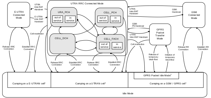
According to UMTS RCC States, each RRC state has following characteristics:
CELL_DCH state is characterised by:
- A dedicated physical channel is allocated to the UE in uplink and downlink.
- The UE is known on cell level according to its current active set.
- Dedicated transport channels, downlink and uplink (TDD) shared transport channels, and a combination of these transport channels can be used by the UE.
CELL_FACH state is characterised by:
- No dedicated physical channel is allocated to the UE.
- The UE continuously monitors a FACH in the downlink.
- The UE is assigned a default common or shared transport channel in the uplink (e.g. RACH) that it can use anytime according to the access procedure for that transport channel.
- The position of the UE is known by UTRAN on cell level according to the cell where the UE last made a cell update.
- In TDD mode, one or several USCH or DSCH transport channels may have been established.
CELL_PCH state is characterised by:
- No dedicated physical channel is allocated to the UE.
- The UE selects a PCH with the algorithm, and uses DRX for monitoring the selected PCH via an associated PICH.
- No uplink activity is possible.
- The position of the UE is known by UTRAN on cell level according to the cell where the UE last made a cell update in CELL_FACH state.
URA_PCH State is characterised by:
- No dedicated physical channel is allocated to the UE.
- The UE selects a PCH with the algorithm, and uses DRX for monitoring the selected PCH via an associated PICH.
- No uplink activity is possible.
- The location of the UE is known on UTRAN Registration area level according to the URA assigned to the UE during the last URA update in CELL_FACH state.
The following figure is Figure 1: Overall Idle Mode process from TS 25.304-8c0 User Equipment (UE) procedures in idle mode and procedures for cell reselection in connected mode:
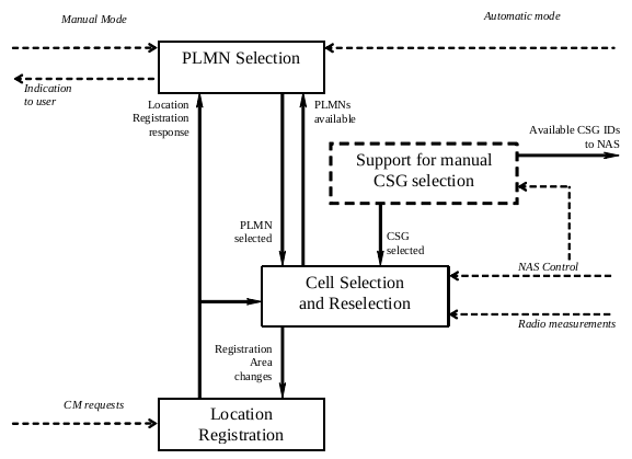
The following figure is Figure 2: Idle Mode Cell Selection and Reselection In any state from TS 25.304-8c0 User Equipment (UE) procedures in idle mode and procedures for cell reselection in connected mode:
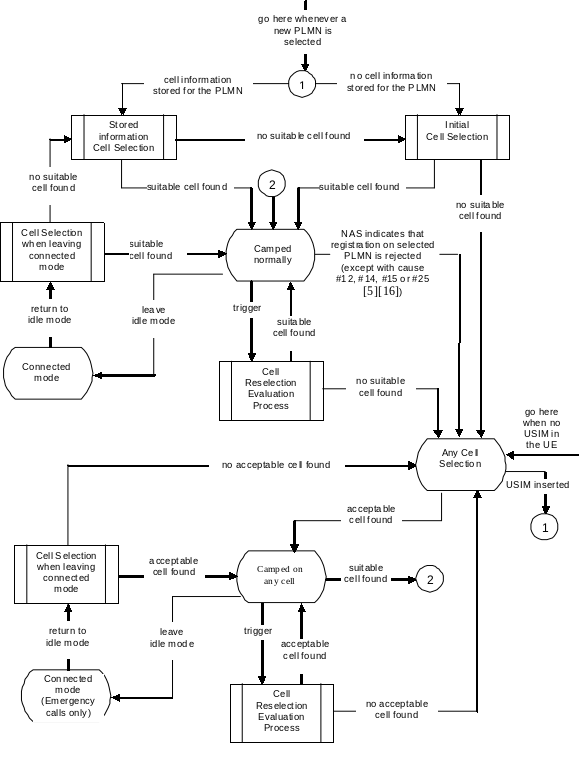
Protocol termination
Protocol termination for DCH
NOTE: The part of physical layer terminating in the Serving RNC is the topmost macrodiversity combining and splitting function for the FDD mode. If no macrodiversity applies, the physical layer is terminated in Node B.
The following figure is Figure 11: Protocol Termination for DCH, control plane from TS 25.301-870 Radio Interface Protocol Architecture:
The following figure is Figure 12: Protocol Termination for DCH, user plane from TS 25.301-870 Radio Interface Protocol Architecture:
Protocol termination for RACH/FACH
The following figure is Figure 13: Protocol Termination for RACH/FACH, control plane from TS 25.301-870 Radio Interface Protocol Architecture:
The following figure is Figure 14: Protocol Termination for RACH/FACH, user plane from TS 25.301-870 Radio Interface Protocol Architecture:
Protocol termination for transport channel of type BCH
The following figure is Figure 21: Protocol termination for BCH from TS 25.301-870 Radio Interface Protocol Architecture:
NOTE: the RLC sublayer is transparent for this transport channel type.
Protocol termination for transport channel of type PCH
The following figure is Figure 22: Protocol termination for PCH from TS 25.301-870 Radio Interface Protocol Architecture:
NOTE: the RLC sublayer is transparent for this channel.
Iub Interface
TS 25.41x - UTRAN Iu interface
- TS 25.410 - UTRAN Iu Interface: General aspects and principles
- TS 25.411 - UTRAN Iu Interface: Layer 1
- TS 25.412 - UTRAN Iu Interface: Signalling transport
- TS 25.413 - UTRAN Iu Interface: Radio Access Network Application Part (RANAP) signalling
- TS 25.414 - UTRAN Iu Interface: Data transport and transport signalling
- TS 25.415 - UTRAN Iu Interface: User plane protocols
- TS 25.419 - UTRAN Iu-BC interface: Service Area Broadcast Protocol (SABP)
Iur Interface
TS 25.42x - UTRAN Iur interface
- TS 25.420 - UTRAN Iur Interface: General aspects and principles
- TS 25.421 - UTRAN Iur Interface: Layer 1
- TS 25.422 - UTRAN Iur Interface: Signalling transport
- TS 25.423 - UTRAN Iur Interface: Radio Network Subsystem Application Part (RNSAP) signalling
- TS 25.424 - UTRAN Iur Interface: Data transport & transport signalling for Common Transport Channel data streams
- TS 25.425 - UTRAN Iur Interface: User plane protocols for Common Transport Channel data streams
- TS 25.426 - UTRAN Iur and Iub interface data transport & transport signalling for DCH data streams
- TS 25.427 - UTRAN Iub/Iur interface user plane protocol for DCH data streams
Iu Interface
TS 25.43x - UTRAN Iub Interface
- TS 25.430 - UTRAN Iub Interface: General aspects and principles
- TS 25.431 - UTRAN Iub Interface: Layer 1
- TS 25.432 - UTRAN Iub Interface: Signalling transport
- TS 25.433 - UTRAN Iub Interface: Node B Application Part (NBAP) signalling
- TS 25.434 - UTRAN Iub Interface: Data transport and transport signalling for Common Transport Channel data streams
- TS 25.435 - UTRAN Iub Interface: User plane protocols for Common Transport Channel data streams
UMTS Core Network (MAP)
MAP for UMTS (3G) and GSM (Release 99 and later) is specified by 3GPP TS 29.002 (MAP v3).
TS 29.xxx - MAP Protocol
- TS 29.002 - Mobile Application Part (MAP) specification
- TS 29.007 - General requirements on interworking between the Public Land Mobile Network (PLMN) and the Integrated Services Digital Network (ISDN) or Public Switched Telephone Network (PSTN)
- TS 29.010 - Information element mapping between MS-BSS and BSS-MSC; Signalling Procedures and the Mobile Application Part (MAP)
- TS 29.011 - Signalling Interworking for supplementary services
- TS 29.013 - Signalling interworking between ISDN supplementary services; Application Service Element (ASE) and Mobile Application Part (MAP) protocols
- TS 29.016 - General Packet Radio Service (GPRS); Serving GPRS Support Node (SGSN) - Visitors Location Register (VLR); Gs interface network service specification
- TS 29.018 - General Packet Radio Service (GPRS); Serving GPRS Support Node (SGSN) - Visitors Location Register (VLR); Gs interface layer 3 specification
UMTS Technical Details
Frequency Bands
According to section 5.2 Frequency bands of TS 25.101-8g0 User Equipment (UE) radio transmission and reception (FDD) from TS 25.101-8g0 User Equipment (UE) radio transmission and reception (FDD), the following frequency bands and TX-RX frequency separation exist:
| Bands | UL Freq UE Tx / Node B Rx (MHz) |
DL Freq UE Rx / Node B Tx (MHz) |
TX-RX Freq Separation (MHz) |
|---|---|---|---|
| I | 1920 - 1980 | 2110 - 2170 | 190 |
| II | 1850 - 1910 | 1930 - 1990 | 80 |
| III | 1710 - 1785 | 1805 - 1880 | 95 |
| IV | 1710 - 1755 | 2110 - 2155 | 400 |
| V | 824 - 849 | 869 - 894 | 45 |
| VI | 830 - 840 | 875 - 885 | 45 |
| VII | 2500 - 2570 | 2620 - 2690 | 120 |
| VIII | 880 - 915 | 925 - 960 | 45 |
| IX | 1749.9 - 1784.9 | 1844.9 - 1879.9 | 95 |
| X | 1710 - 1770 | 2110 - 2170 | 400 |
| XI | 1427.9 - 1447.9 | 1475.9 - 1495.9 | 48 |
| XII | 699 - 716 | 729 - 746 | 30 |
| XIII | 777 - 787 | 746 - 756 | 31 |
| XIV | 788 - 798 | 758 - 768 | 30 |
UARFCN
The UTRA Absolute Radio Frequency Channel Number (UARFCN) is the channel number representing the full 5 MHz UMTS carrier. The nominal channel spacing is 5 MHz, but this can be adjusted to optimise performance in a particular deployment scenario. In a 5 MHz channel, only 3.84MHz is used for transmission, while the 1.16 MHz acts as a built-in guard-band to adjacent UARFCN’s (580 kHz + 3840 kHz + 580 kHz = 5 MHz). If an operator owns the adjacent frequency bands, it is possible to reduce the size of the UMTS carrier from 5MHz to 4.4 or 4.2 MHZ, but this is not recommended.
The UARFCN and UMTS carrier frequencies can be transformed by Frequency Calculator.
Also refer to following tables of TS 25.101-8g0 User Equipment (UE) radio transmission and reception (FDD) for details of frequency bands and UARFCN:
- Table 5.1: UARFCN definition (general)
- Table 5.1A: UARFCN definition (additional channels)
- Table 5.2: UTRA Absolute Radio Frequency Channel Number
Different Type of Cells
According to section 4.3 Service type in Idle and Connected Mode of TS 25.304-8c0 User Equipment (UE) procedures in idle mode and procedures for cell reselection in connected mode, the following types of cells exist:
-
Acceptable Cell
An Acceptable Cell is a cell on which the UE may camp to obtain limited service (originate emergency calls and receive ETWS if supported). Such a cell shall fulfil the following requirements
- The cell is not barred;
- Cell selection criteria are fulfilled.
-
Suitable Cell
Suitable cell is a cell on which UE can camp on to provide normal service. Suitable cell satisfies some criteria:
- The cell should be part of the selected PLMN, or registered PLMN, or equivalent PLMN;
- The cell is not barred;
- The cell is part of at least one LA which is not part of the forbidden LA list;
- The cell selection criteria are full filled.
-
Barred Cell
The UE is not allowed to camp on a barred cell. System information 3 indicates whether a cell is barred or not.
-
Reserved Cell
This is a cell on which camping is not allowed. Only particular UE are allowed to camp on a reserved cell.
System Information
Refer to following sections of TS 25.331-8l0 Radio Resource Control (RRC) protocol specification for system information:
- S8.1.1 Broadcast of system information
- S10.2.48 SYSTEM INFORMATION
The system information includes following types:
MIB (Master Information Block)
A master information block (MIB) gives references and scheduling information to a number of system information blocks (SIBs) in a cell. It may optionally also contain reference and scheduling information to one or two scheduling blocks (SB), which give references and scheduling information for additional system information blocks (SIBs).
According to following parameters of Table 8.1.1: Specification of system information block characteristics from TS 25.331-8l0 Radio Resource Control (RRC) protocol specification:
SIB_POS = 0
SIB_REP = 8 (FDD)
SIB_REP = 8, 16, 32 (TDD)
SIB_OFF = 2
and Scheduling of system information, the repetition period of master information block (MIB) is 80ms, that’s, 8 frames for FDD mode.
SB (Scheduling Block)
Scheduling information for a system information block (SIB) may only be included in either the master information block (MIB) or one of the scheduling blocks (SB).
SIB (System Information Block)
The system information blocks (SIBs) contain the actual system information. According to section 10.2.48.8.2 - 10.2.48.8.23 from TS 25.331-8l0 Radio Resource Control (RRC) protocol specification, the following types of SIBs exist:
| SIB_Types | Description |
|---|---|
| SIB 1 | The system information block type 1 contains NAS system information as well as UE timers and counters to be used in idle mode and in connected mode. |
| SIB 2 | The system information block type 2 contains the URA identity. |
| SIB 3 | The system information block type 3 contains parameters for cell selection and re-selection. |
| SIB 4 | The system information block type 4 contains parameters for cell selection and re-selection to be used in connected mode. |
| SIB 5 | The system information block type 5 contains parameters for the configuration of the common physical channels in the cell. |
| SIB 5bis | The system information block type 5bis uses the same structure as System information block type 5. System information block type 5bis is sent instead of system information block type 5 in cells that use Band IV or Band IX or Band X. |
| SIB 6 | The system information block type 6 contains parameters for the configuration of the common and shared physical channels to be used in connected mode. |
| SIB 7 | The system information block type 7 contains the fast changing parameters UL interference and Dynamic persistence level. |
| SIB 11 | The system information block type 11 contains measurement control information to be used in the cell. |
| SIB 11bis | The system information block type 11bis contains measurement control information to be used in the cell in addition to System Information Block type 11 and optionally UTRAN mobility information for CSG cells. |
| SIB 12 | The system information block type 12 contains measurement control information to be used in connected mode. |
| SIB 13 | The system information block type 13 contains ANSI-41 system information. |
| SIB 13.1 | The system information block type 13.1 contains the ANSI-41 RAND information. |
| SIB 13.2 | The system information block type 13.2 contains the ANSI-41 User Zone Identification information. |
| SIB 13.3 | The system information block type 13.3 contains the ANSI-41 Private Neighbour List information. |
| SIB 13.4 | The system information block type 13.4 contains the ANSI-41 Global Service Redirection information. |
| SIB 14 | The system information block type 14 contains parameters for common and dedicated physical channel uplink outer loop power control information to be used in both idle and connected mode. NOTE: Only for 3.84 Mcps TDD and 7.68 Mcps TDD. |
| SIB 15 | The system information block type 15 contains information useful for UE-based or UE-assisted positioning methods. |
| SIB 15bis | The system information block type 15bis contains information useful for UE-based or UE-assisted positioning methods. The content of this SIB is common to all GANSS. |
| SIB 15.1 | The system information block type 15.1 contains information useful for UE positioning DGPS Corrections. |
| SIB 15.1bis | The system information block type 15.1bis contains information useful for UE positioning DGANSS Corrections. |
| SIB 15.2 | The system information block type 15.2 contains information useful for GPS Navigation Model. |
| SIB 15.2bis | The system information block type 15.2bis contains information useful for GANSS Navigation Model. The content of this SIB is GNSS specific. |
| SIB 15.2ter | The system information block type 15.2ter contains information useful for GANSS Navigation Model. The content of this SIB is GNSS specific. |
| SIB 15.3 | The system information block type 15.3 contains information useful for ionospheric delay, UTC offset, and Almanac. |
| SIB 15.3bis | The system information block type 15.3bis contains information useful for GANSS time model, UTC offset and Almanac, as well as auxiliary information. The content of this SIB is GNSS specific. |
| SIB 15.4 | The system information block type 15.4 contains ciphering information for System Information Block type 15.5 and information useful for OTDOA UE-assisted Positioning method. |
| SIB 15.5 | The system information block type 15.5 contains information useful for OTDOA UE-based Positioning method. |
| SIB 15.6 | The system information block type 15.6 contains information useful for acquisition of GANSS signals. The content of this SIB is GNSS specific. |
| SIB 15.7 | The system information block type 15.7 contains data bits which can be used for data wipe-off. The content of this SIB is GNSS specific. |
| SIB 15.8 | The system information block type 15.8 contains ciphering information and real-time integrity information. The content of this SIB is GNSS specific. |
| SIB 16 | The system information block type 16 contains radio bearer, transport channel and physical channel parameters to be stored by UE in idle and connected mode for use during handover to UTRAN. |
| SIB 17 | The system information block type 17 contains fast changing parameters for the configuration of the shared physical channels to be used in connected mode. NOTE: Only for TDD. |
| SIB 18 | The System Information Block type 18 contains PLMN identities of neighbouring cells to be considered in idle mode as well as in connected mode. |
| SIB 19 | The system information block type 19 contains Inter-RAT frequency and priority information to be used in the cell. |
| SIB 20 | The system information block type20 contains HNBName. |
Scheduling of system information
| Parameters | Description |
|---|---|
| SEG_COUNT | The number of segments. |
| SIB_REP | The repetition period. The same value applies to all segments. |
| SIB_POS(0) | The position (phase) of the first segment within one cycle of the Cell System Frame Number (SFN). |
| SIB_OFF(i) | The offset of the subsequent segments in ascending index order, that’s SIB_POS(i) = SIB_POS(i-1) + SIB_OFF(i), i = 0, 1, 2, … SEG_COUNT-1 |
The scheduling is based on the Cell System Frame Number (SFN). The SFN of a frame at which a particular segment, i, with i = 0, 1, 2, … SEG_COUNT-1 of a system information block occurs, fulfils the following relation:
SFN mod SIB_REP = SIB_POS(i)
Procedures
-
TS 25.304-8c0 User Equipment (UE) procedures in idle mode and procedures for cell reselection in connected mode
- S5.1 PLMN selection
-
TS 25.303-800 Interlayer procedures in Connected Mode
- S6.1.1 RRC connection establishment
- S6.1.2 UE Initiated Signalling Connection Establishment
- S6.1.3 Normal RRC Connection Release
- S6.2.1 Radio Bearer Configuration
- S6.2.1.2 Radio Bearer Release
- S6.2.1.3 Radio Bearer Reconfiguration
- S6.2.2 Transport Channel Reconfiguration
- S6.2.3 Physical Channel Reconfiguration
- S6.2.4 Transport Format Combination Control
- S6.4 RRC Connection mobility procedures
- S6.4.1 Handover Measurement Reporting
- S6.4.2 Cell Update
- S6.4.3 URA Update
- S6.4.4 Radio Link Addition (FDD)
- S6.4.5 Radio Link Removal (FDD)
- S6.4.6 Combined radio link addition and removal
- S6.4.7 Hard Handover (FDD and TDD)
- S6.4.8 SRNS Relocation
- S6.4.9 RRC Connection re-establishment
- S6.4.10 Inter-system Handover: GSM/BSS to UTRAN
- S6.5 CN originated paging request in connected mode
- S6.6 UTRAN originated paging request and paging response
- S6.7.1 UE Capability Information
- S6.7.2 Random access transmission sequence (FDD)
- S6.7.3 Random access transmission sequence (TDD)
- S7 Traffic volume monitoring procedure
-
TS 23.122 - NAS functions related to Mobile Station (MS) in idle mode
Cell Selection
Basic Procedure - LTE Cell Selection
HSPA
High Speed Packet Access (HSPA) is an amalgamation of two mobile protocols, High Speed Downlink Packet Access (HSDPA) and High Speed Uplink Packet Access (HSUPA), that extends and improves the performance of existing 3G mobile telecommunication networks utilizing the WCDMA protocols. A further improved 3GPP standard, Evolved High Speed Packet Access (also known as HSPA+), was released late in 2008 with subsequent worldwide adoption beginning in 2010. The newer standard allows bit-rates to reach as high as 337 Mbit/s in the downlink and 34 Mbit/s in the uplink. However, these speeds are rarely achieved in practice.
HSDPA (3.5G)
HSDPA is part of the UMTS standards since R5.
Standards
Table 5.1a of the release 11 of 3GPP TS 25.306
The second phase of HSDPA is specified in the 3GPP release 7 and has been named HSPA Evolved.
- TS 25.308 - HSDPA Overall Description; Stage 2
HSUPA
HSDP+ (3.75G)
IMS
The following figure is Figure 6: Configuration of IM Subsystem entities from 3GPP TS 23.002-5c0 Network Architecture: