UART: Universal Asynchronous Receiver/Transmitter
This article introduces the UART (Universal Asynchronous Receiver/Transmitter).
Overview
A Universal Asynchronous Receiver/Transmitter (UART) is a computer hardware device for asynchronous serial communication in which the data format and transmission speeds are configurable. The electric signaling levels and methods are handled by a driver circuit external to the UART. A UART is usually an individual (or part of an) integrated circuit (IC) used for serial communications over a computer or peripheral device serial port. UARTs are now commonly included in microcontrollers. A related device, the Universal Synchronous/Asynchronous Receiver/Transmitter (USART) also supports synchronous operation.
History
Some early telegraph schemes used variable-length pulses (as in Morse code) and rotating clockwork mechanisms to transmit alphabetic characters. The first serial communication devices (with fixed-length pulses) were rotating mechanical switches (commutators). Various character codes using 5, 6, 7, or 8 data bits became common in teleprinters and later as computer peripherals. The teletypewriter made an excellent general-purpose I/O device for a small computer.
Gordon Bell of DEC designed the first UART, occupying an entire circuit board called a line unit, for the PDP series of computers beginning with the PDP-1. According to Bell, the main innovation of the UART was its use of sampling to convert the signal into the digital domain, allowing more reliable timing than previous circuits that used analog timing devices with manually adjusted potentiometers. To reduce the cost of wiring, backplane and other components, these computers also pioneered flow control using XON and XOFF characters rather than hardware wires.
DEC condensed the line unit design into an early single-chip UART for their own use. Western Digital developed this into the first widely available single-chip UART, the WD1402A, around 1971. This was an early example of a medium scale integrated circuit. Another popular chip was the SCN2651 from the Signetics 2650 family.
An example of an early 1980s UART was the National Semiconductor 8250. In the 1990s, newer UARTs were developed with on-chip buffers. This allowed higher transmission speed without data loss and without requiring such frequent attention from the computer. For example, the popular National Semiconductor 16550 has a 16 byte FIFO, and spawned many variants, including the 16C550, 16C650, 16C750, and 16C850.
Depending on the manufacturer, different terms are used to identify devices that perform the UART functions. Intel called their 8251 device a “Programmable Communication Interface”. MOS Technology 6551 was known under the name “Asynchronous Communications Interface Adapter” (ACIA). The term “Serial Communications Interface” (SCI) was first used at Motorola around 1975 to refer to their start-stop asynchronous serial interface device, which others were calling a UART. Zilog manufactured a number of Serial Communication Controllers or SCCs.
After the RS-232 COM port was removed from most IBM PC compatible computers in the 2000s, an external USB-to-UART serial adapter cable was used to compensate for the loss. A major supplier of these chips is FTDI.
Structure
A UART usually contains the following components:
- a clock generator, usually a multiple of the bit rate to allow sampling in the middle of a bit period.
- input and output shift registers
- transmit/receive control
- read/write control logic
- transmit/receive buffers (optional)
- system data bus buffer (optional)
- First-in, first-out (FIFO) buffer memory (optional)
- Signals needed by a third party DMA controller (optional)
- Integrated bus mastering DMA controller (optional)
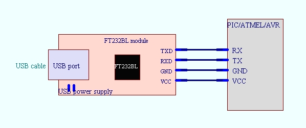
| Pin | Description |
|---|---|
| VCC | 供电引脚,一般是3.3v |
| GND | 接地引脚,有的时候 RX 接收数据有问题,就要接上这个引脚,一般也可不接 |
| RX | 接收数据引脚 |
| TX | 发送数据引脚 |
Transmit/Receive Serial Data
The Universal Asynchronous Receiver/Transmitter (UART) takes bytes of data and transmits the individual bits in a sequential fashion. At the destination, a second UART re-assembles the bits into complete bytes. Each UART contains a shift register, which is the fundamental method of conversion between serial and parallel forms. Serial transmission of digital information (bits) through a single wire or other medium is less costly than parallel transmission through multiple wires.
The UART usually does not directly generate or receive the external signals used between different items of equipment. Separate interface devices are used to convert the logic level signals of the UART to and from the external signalling levels, which may be standardized voltage levels, current levels, or other signals.
Communication may be simplex (in one direction only, with no provision for the receiving device to send information back to the transmitting device), full duplex (both devices send and receive at the same time) or half duplex (devices take turns transmitting and receiving).
Data Framing

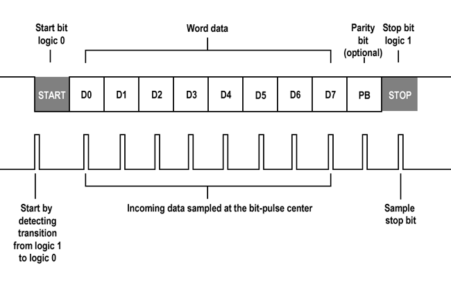
The idle, no data state is high-voltage, or powered. This is a historic legacy from telegraphy, in which the line is held high to show that the line and transmitter are not damaged. Each character is framed as a logic low start bit, data bits, possibly a parity bit, and one or more stop bits. In most applications the least significant data bit (the one on the left in this diagram) is transmitted first, but there are exceptions (such as the IBM 2741 printing terminal).
The start bit signals the receiver that a new character is coming. The next five to nine bits, depending on the code set employed, represent the character. If a parity bit is used, it would be placed after all of the data bits. The next one or two bits are always in the mark (logic high, i.e., ‘1’) condition and called the stop bit(s). They signal the receiver that the character is completed. Since the start bit is logic low (0) and the stop bit is logic high (1) there are always at least two guaranteed signal changes between characters.
If the line is held in the logic low condition for longer than a character time, this is a break condition that can be detected by the UART.
Receiver
All operations of the UART hardware are controlled by a clock signal which runs at a multiple of the data rate, typically 8 times the bit rate. The receiver tests the state of the incoming signal on each clock pulse, looking for the beginning of the start bit. If the apparent start bit lasts at least one-half of the bit time, it is valid and signals the start of a new character. If not, it is considered a spurious pulse and is ignored. After waiting a further bit time, the state of the line is again sampled and the resulting level clocked into a shift register. After the required number of bit periods for the character length (5 to 8 bits, typically) have elapsed, the contents of the shift register are made available (in parallel fashion) to the receiving system. The UART will set a flag indicating new data is available, and may also generate a processor interrupt to request that the host processor transfers the received data.
Communicating UARTs usually have no shared timing system apart from the communication signal. Typically, UARTs resynchronize their internal clocks on each change of the data line that is not considered a spurious pulse. Obtaining timing information in this manner, they reliably receive when the transmitter is sending at a slightly different speed than it should. Simplistic UARTs do not do this, instead they resynchronize on the falling edge of the start bit only, and then read the center of each expected data bit, and this system works if the broadcast data rate is accurate enough to allow the stop bits to be sampled reliably.
It is a standard feature for a UART to store the most recent character while receiving the next. This “double buffering” gives a receiving computer an entire character transmission time to fetch a received character. Many UARTs have a small first-in, first-out FIFO buffer memory between the receiver shift register and the host system interface. This allows the host processor even more time to handle an interrupt from the UART and prevents loss of received data at high rates.
Transmitter
Transmission operation is simpler as the timing does not have to be determined from the line state, nor is it bound to any fixed timing intervals. As soon as the sending system deposits a character in the shift register (after completion of the previous character), the UART generates a start bit, shifts the required number of data bits out to the line, generates and sends the parity bit (if used), and sends the stop bits. Since full-duplex operation requires characters to be sent and received at the same time, UARTs use two different shift registers for transmitted and received characters. High performance UARTs could contain a transmit FIFO (first in first out) buffer to allow a CPU or DMA controller to deposit multiple characters in a burst into the FIFO rather than have to deposit one character at a time into the FIFO. Since transmission of a single or multiple characters may take a long time relative to CPU speeds, a UART maintains a flag showing busy status so that the host system knows if there is at least one character in the transmit buffer or shift register; “ready for next character(s)” may also be signaled with an interrupt.
Application
Transmitting and receiving UARTs must be set for the same bit speed, character length, parity, and stop bits for proper operation. The receiving UART may detect some mismatched settings and set a “framing error” flag bit for the host system; in exceptional cases the receiving UART will produce an erratic stream of mutilated characters and transfer them to the host system.
Typical serial ports used with personal computers connected to modems use eight data bits, no parity, and one stop bit; for this configuration the number of ASCII characters per second equals the bit rate divided by 10.
Some very low-cost home computers or embedded systems dispense with a UART and use the CPU to sample the state of an input port or directly manipulate an output port for data transmission. While very CPU-intensive (since the CPU timing is critical), the UART chip can thus be omitted, saving money and space. The technique is known as bit-banging.
UART in Modems
Modems for personal computers that plug into a motherboard slot must also include the UART function on the card. The original 8250 UART chip shipped with the IBM personal computer had a one character buffer for the receiver and the transmitter each, which meant that communications software performed poorly at speeds above 9600 bits/second, especially if operating under a multitasking system or if handling interrupts from disk controllers. High-speed modems used UARTs that were compatible with the original chip but which included additional FIFO buffers, giving software additional time to respond to incoming data.
A look at the performance requirements at high bit rates shows why the 16, 32, 64 or 128 byte FIFO is a necessity. The Microsoft specification for a DOS system requires that interrupts not be disabled for more than 1 millisecond at a time. Some hard disk drives and video controllers violate this specification. 9600 bit/s will deliver a character approximately every millisecond, so a 1 byte FIFO should be sufficient at this rate on a DOS system which meets the maximum interrupt disable timing. Rates above this may receive a new character before the old one has been fetched, and thus the old character will be lost. This is referred to as an overrun error and results in one or more lost characters.
A 16 byte FIFO allows up to 16 characters to be received before the computer has to service the interrupt. This increases the maximum bit rate the computer can process reliably from 9600 to 153,000 bit/s if it has a 1 millisecond interrupt dead time. A 32 byte FIFO increases the maximum rate to over 300,000 bit/s. A second benefit to having a FIFO is that the computer only has to service about 8 to 12% as many interrupts, allowing more CPU time for updating the screen, or doing other chores. Thus the computer’s responses will improve as well.