Telecom: GSM
This article introduce the GSM definded by 3GPP.
History
The following table shows some of the important events in the rollout of the GSM system.
| Years | Events |
|---|---|
| 1982 | Conference of European Posts and Telegraph (CEPT) establishes a GSM group to widen the standards for a pan-European cellular mobile system. |
| 1985 | A list of recommendations to be generated by the group is accepted. |
| 1986 | Executed field tests to check the different radio techniques recommended for the air interface. |
| 1987 | Time Division Multiple Access (TDMA) is chosen as the access method (with Frequency Division Multiple Access [FDMA]). The initial Memorandum of Understanding (MoU) is signed by telecommunication operators representing 12 countries. |
| 1988 | GSM system is validated. |
| 1989 | The European Telecommunications Standards Institute (ETSI) was given the responsibility of the GSM specifications. |
| 1990 | Phase 1 of the GSM specifications is delivered. |
| 1991 | Commercial launch of the GSM service occurs. The DCS1800 specifications are finalized. |
| 1992 | The addition of the countries that signed the GSM MoU takes place. Coverage spreads to larger cities and airports. |
| 1993 | Coverage of main roads GSM services starts outside Europe. |
| 1994 | Data transmission capabilities launched. The number of networks rises to 69 in 43 countries by the end of 1994. |
| 1995 | Phase 2 of the GSM specifications occurs. Coverage is extended to rural areas. |
| 1996 | June: 133 network in 81 countries operational. |
| 1997 | July: 200 network in 109 countries operational, around 44 million subscribers worldwide. |
| 1999 | Wireless Application Protocol (WAP) came into existence and became operational in 130 countries with 260 million subscribers. |
| 2000 | General Packet Radio Service (GPRS) came into existence. |
| 2001 | As of May 2001, over 550 million people were subscribers to mobile telecommunications. |
| 2002 | The first Multimedia Messaging Service (MMS) were introduced and the first GSM network in the 800 MHz frequency band became operational. |
| 2003 | Enhanced Data rates for GSM Evolution (EDGE) services first became operational in a network. |
| 2004 | The number of worldwide GSM subscribers exceeded 1 billion. |
| 2015 | Macau planned to phase out its 2G GSM networks as of June 4, 2015, making it the first region to decommission a GSM network. |
Also refer to GSM History.
Standards
Refer to the table in section Specification Numbering for the GSM standards, and the table in section 3GPP Standards for the GSM features in each Release.
Network Structure
| GSM Radio access network | GSM/EDGE Radio Access Network (GERAN) |
| GSM Core network | Mobile Application Part (MAP) |
The following figure shows the GSM network structure, which is got from wikipedia:

Also refer to GSM Network Architecture for details in R4.
The following figure is UMTS domains and reference points from Rel-99_description_20160701:

R99 Network Structure
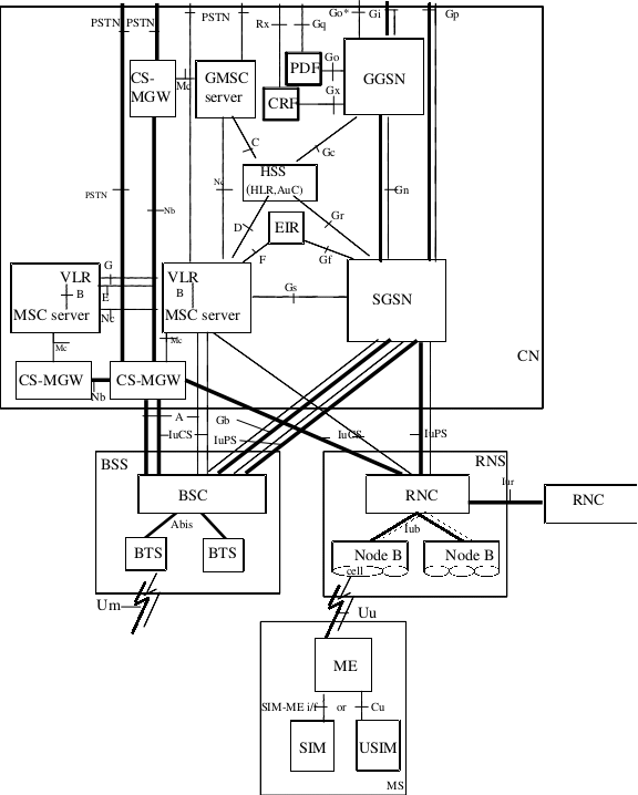
The following figure is UMTS and GSM Network Architecture from Rel-99_description_20160701:
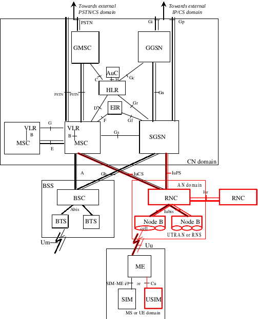
Compare to R98, the entities in read blocks are new added.
R4 Network Structure
GSM Network Architecture
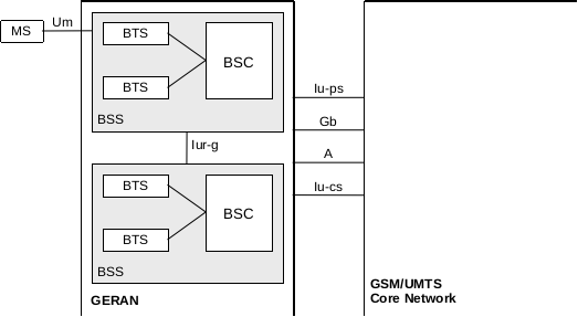
The following figure is Figure 1: GERAN reference architecture from TS 43.051-400 GSM/EDGE Radio Access Network (GERAN); Overall Description - Stage 2:
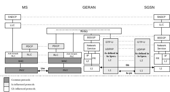
The following figure is Figure 4: User Plane protocols towards Packet Switched Core Network domain from TS 43.051-400 GSM/EDGE Radio Access Network (GERAN); Overall Description - Stage 2:
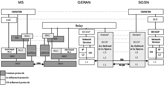
The following figure is Figure 5: Control Plane protocols towards Packet Switched Core Network domain from TS 43.051-400 GSM/EDGE Radio Access Network (GERAN); Overall Description - Stage 2:
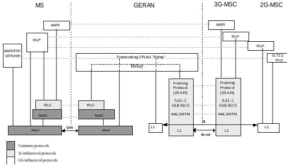
The following figure is Figure 6: User Plane protocols towards Circuit-Switched Core Network domain from TS 43.051-400 GSM/EDGE Radio Access Network (GERAN); Overall Description - Stage 2:
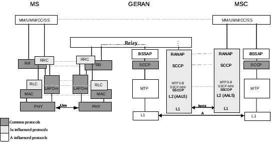
The following figure is Figure 7: Control Plane Protocols towards Circuit-Switched Core Network Domain from TS 43.051-400 GSM/EDGE Radio Access Network (GERAN); Overall Description - Stage 2:
R5 Network Structure
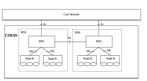
The following figure is Figure 4: UTRAN Architecture from TS 25.401-5a0 UTRAN overall description:
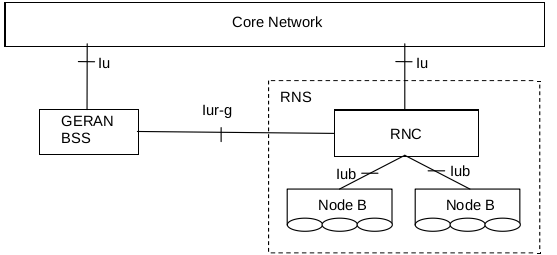
The following figure is Figure 4b: UTRAN and GERAN Iu mode connection with Iur-g from TS 25.401-5a0 UTRAN overall description:
The following figure is Figure 1: Basic Configuration of a PLMN supporting CS and PS services and interfaces from TS 23.002-5c0 Network Architecture:

Compare to R4, the entities HLR and AuC are merged into entity HSS, and interfaces IuCS and IuPS are new added to BSC.
R6 Network Structure
The following figure is Figure 1: Basic Configuration of a PLMN supporting CS and PS services and interfaces from TS 23.002-6a0 Network Architecture:
Compare to R5, the entities CRF (Charging Rules Function), PDF (Policy Decision Function) and corresponding interfaces are new added.
R7 Network Structure
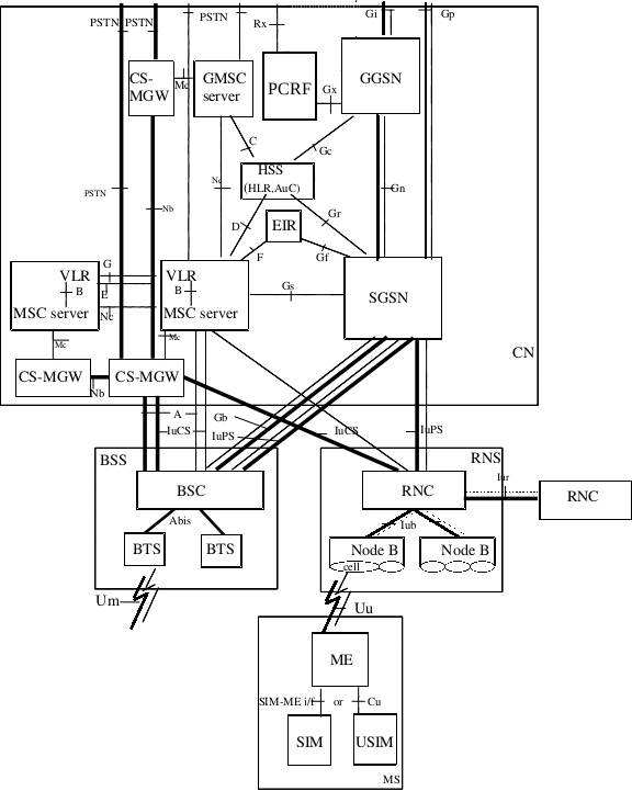
The following figure is Figure 1: Basic Configuration of a PLMN supporting CS and PS services and interfaces from TS 23.002-760 Network Architecture:

Compare to R6, the entities PDF (Policy Decision Function) and CRF (Charging Rules Function) are merged into PCRF (Policy and Charging Rules Function).
R8 Network Structure
The following figure is Figure 1: Basic Configuration of a PLMN supporting CS and PS services and interfaces from TS 23.002-870 Network Architecture:

The network structure in R8 is the same to that in R7.
R9 Network Structure
The following figure is Figure 1: Basic Configuration of a PLMN supporting CS and PS services and interfaces from TS 23.002-960 Network Architecture:
The network structure in R9 is the same to that in R7 and R8.
R10 Network Structure
The following figure is Figure 1: Basic Configuration of a PLMN supporting CS and PS services and interfaces from TS 23.002-a30 Network Architecture:

The network structure in R10 is the same to that in R7, R8 and R9.
R11 Network Structure
The following figure is Figure 1: Basic Configuration of a PLMN supporting CS and PS services and interfaces from TS 23.002-b00 Network Architecture:

The network structure in R11 is the same to that in R7, R8, R9 and R10.
R12 Network Structure
The following figure is Figure 1: Basic Configuration of a PLMN supporting CS and PS services and interfaces from TS 23.002-c70 Network Architecture:

The network structure in R12 is the same to that in R7, R8, R9, R10 and R11.
R13 Network Structure
The following figure is Figure 1: Basic Configuration of a PLMN supporting CS and PS services and interfaces from TS 23.002-d50 Network Architecture:

The network structure in R13 is the same to that in R7, R8, R9, R10, R11 and R12.
Interfaces
The following table shows the interfaces between difference nodes in GSM network:
| Interfaces | Connected Nodes | Protocols | Related Specs |
|---|---|---|---|
| Um | ME - BTS | ||
| Abis | BTS - BSC | ||
| A | MSC - BSC | BSSAP | |
| B | MSC - VLR | ||
| C | MSC - HLR | MAP | |
| D | VLR - HLR | MAP | |
| E | MSC - MSC | MAP | |
| F | MSC - EIR | MAP | |
| G | VLR - VLR | MAP | |
| Gs | MSC - SGSN | BSSAP+ | |
| H | HLR - AuC | ||
| MSC - PSTN/ISDN/PSPDN | TUP/ISUP | ||
| Ga | GSN - CG | GTP | |
| Gb | SGSN - BSC | BSSGP | |
| Gc | GGSN - HLR | MAP | |
| Gd | SGSN - SMS-GMSC/IWMSC | MAP | |
| Ge | SGSN - SCP | CAP | |
| Gf | SGSN - EIR | MAP | |
| Gi | GGSN - PDN | TCP/IP | |
| Gp | GSN - GSN (Inter PLMN) | GTP | |
| Gn | GSN - GSN (Intra PLMN) | GTP | |
| Gr | SGSN - HLR | MAP |
The following table shows the interfaces in GSM/UMTS/LTE networks, refer to section 6 PLMN basic interfaces and reference points of TS 23.002-870 Network architecture:
| RAN | Interfaces | Connected_Entries | Protocol | Releases | Specs |
|---|---|---|---|---|---|
| UTRAN | Cu | USIM – ME | |||
| GERAN | Um | MS – BSS | TS 44-series, TS 45-series, TS 44.071 | ||
| UTRAN | Uu | UE – RNS | TS 24-series, TS 25-series, TS 25.305 | ||
| E-UTRAN | Uu | UE – E-UTRAN | TS 36-series | ||
| GERAN | Abis | BTS – BSC | TS 48.5xx-series | ||
| UTRAN | Iub | NodeB – RNC | TS 25.43x-series | ||
| UTRAN | Iur | RNC – RNC | TS 25.42x-series | ||
| E-UTRAN | X2 | eNB – eNB | TS 36.42x-series | ||
| GERAN | A | BSS – MSC | TS 48-series | ||
| GERAN | Gb | BSS – SGSN | TS 48.014, TS 48.016, TS 48.018 | ||
| GERAN | IuCS | BSS – MSC | RANAP | TS 25.41x-series | |
| GERAN | IuPS | BSS – SGSN | RANAP | TS 25.41x-series | |
| UTRAN | IuCS | RNS – MSC | RANAP | TS 25.41x-series | |
| UTRAN | IuPS | RNS – SGSN | RANAP | TS 25.41x-series | |
| UTRAN | Iupc | SRNC – SAS | TS 25.453 | ||
| E-UTRAN | S1-MME | E-UTRAN – MME | TS 36.41x-series, TS 24.301 | ||
| E-UTRAN | S1-U | E-UTRAN – S-GW | TS 29.274 | ||
| GERAN | B | MSC – VLR | Not standardised | ||
| GERAN | C | GMSC – HLR | MAP | TS 29.002, TS 23.078 | |
| GERAN UTRAN E-UTRAN |
D | HLR – VLR | MAP | TS 29.002, TS 23.078 | |
| GERAN UTRAN E-UTRAN |
E | MSC – MSC MSC – IP-SM-GW |
MAP | TS 29.002, TS 23.009 | |
| GERAN UTRAN E-UTRAN |
F | MSC – EIR | MAP | TS 29.002 | |
| GERAN UTRAN E-UTRAN |
G | VLR – VLR | MAP | TS 29.002 | |
| UTRAN | Mc | MSC – CS-MGW GMSC – CS-MGW |
H.248/IETF Megaco | ||
| UTRAN | Nc | MSC – GMSC | |||
| UTRAN | Nb | CS-MGW – CS-MGW | RTP/UDP/IP, or AAL2 | ||
| UTRAN | Gr | CS-MGW – CS-MGW | MAP, TCAP | TS 29.002 | |
| UTRAN | Gn | SGSN – GGSN (Intra PLMN) | UDP/IP | TS 29.060 | |
| UTRAN | Gp | SGSN – GGSN (Inter PLMN) | UDP/IP | TS 29.060 | |
| UTRAN | Gc | GGSN – HLR | MAP, TCAP | TS 29.002 | |
| UTRAN | Gf | SGSN – EIR | MAP, TCAP | TS 29.002 | |
| UTRAN | Gs | SGSN – MSC/VLR | SCCP, BSSAP+ | TS 29.016, TS 29.018 | |
| UTRAN | H | HLR/HSS – AuC | Not standardised | ||
| UTRAN | Gd | SGSN/IP-SM-GW – SMS-GMSC/SMS-IWMSC | MAP | TS 29.002 | |
| E-UTRAN | SGs | MSC/VLR – MME | SCTP | TS 23.272, TS 29.118 | |
| E-UTRAN | Sv | MSC/VLR – MME | TS 29.280 | ||
| E-UTRAN | S6a | MME – HSS | Diameter S6a/S6d | TS 29.272 | |
| E-UTRAN | S6d | SGSN – HSS | Diameter S6a/S6d | TS 29.272 | |
| E-UTRAN | S11 | MME – S-GW | TS 29.274 | ||
| E-UTRAN | S10 | MME – MME | TS 29.274 | ||
| E-UTRAN | S5/S8 | S-GW – PDN-GW | GTP, PMIP | TS 29.274, TS 29.275 | |
| E-UTRAN | S13 | MME – EIR | Diameter S13 | TS 29.272 | |
| E-UTRAN | S3 | MME – SGSN | TS 29.274 | ||
| E-UTRAN | S4 | S-GW – SGSN | TS 29.274 | ||
| E-UTRAN | S12 | S-GW – UTRAN | GTP-U | TS 29.274 | |
| E-UTRAN | S2a | Trusted non-3GPP IP Access – S-GW/P-GW | TS 29.275, TS 24.304 | ||
| E-UTRAN | S2b | PDN-GW/S-GW – ePDG | TS 29.275, TS 24.304 | ||
| E-UTRAN | S2c | UE – PDN-GW | TS 24.303 | ||
| E-UTRAN | S6b | 3GPP AAA Server/proxy – PDN-GW | TS 29.273 | ||
| E-UTRAN | SWa | 3GPP AAA Server/proxy – Untrusted non-3GPP IP Access | TS 29.273 | ||
| E-UTRAN | STa | 3GPP AAA Server/proxy – Trusted non-3GPP IP Access | TS 29.273 | ||
| E-UTRAN | SWd | 3GPP AAA Server – 3GPP AAA proxy | TS 29.273 | ||
| E-UTRAN | SWm | ePDG – 3GPP AAA Server/proxy | TS 29.273 | ||
| E-UTRAN | SWn | ePDG – Untrusted non-3GPP Access | TS 29.273 | ||
| E-UTRAN | SWu | ePDG – UE | TS 24.302 | ||
| E-UTRAN | SWx | HSS – 3GPP AAA Server | TS 29.273 | ||
| E-UTRAN | S14 | UE – ANDSF | TS 24.302 | ||
| E-UTRAN | S101 | HRDP AN – MME | TS 23.402, 3GPP2 C.S0087 0 | ||
| E-UTRAN | S102 | 3GPP2 1xCS IWF – MME | TS 23.216, TS 23.272, TS 23.402, 3GPP2 A.S0008-C | ||
| E-UTRAN | S103 | HSGW – S-GW | TS 23.402 | ||
| GETRAN | I | MSC – GCR | Not standardised | ||
| GETRAN | Lb | BSC – SMLC | TS 49.031 | ||
| GETRAN | Lp | SMLC – SMLC | BSSAPP-LE, SMLCPP | TS 49.031, TS 48.031 | |
| GETRAN | Le | GMLC – External LCS Client | MLP, OMA MLP TS, OSA-API | TS 29.198 | |
| GETRAN | Lr | GMLC – GMLC | RLP | ||
| GETRAN | GMSC – gsmSSF | TS 23.078 | |||
| GETRAN | gsmSSF – gsmSCF | TS 23.078 | |||
| GETRAN | gsmSSF – MSC | TS 23.078 | |||
| GETRAN | gsmSCF – HLR | TS 23.078 | |||
| GETRAN | gsmSCF – gsmSRF | TS 23.078 | |||
| GETRAN | gsmSCF – MSC | TS 23.078 | |||
| GETRAN | gprsSSF – SGSN | TS 23.078 | |||
| GETRAN | gprsSSF – gsmSCF | TS 23.078 | |||
| UTRAN | CBC – RNS | TS 25.41x-series | |||
| UTRAN | CBC – MME | TS 2x.xxx | |||
| UTRAN | NPDB – MSC | ||||
| UTRAN | MNP-SRF – GMSC | ||||
| UTRAN | MNP-SRF – HLR | ||||
| UTRAN | Cx | CSCF – HSS | TS 23.228 | ||
| UTRAN | Gm | CSCF – UE | SIP | RFC 3261 | |
| UTRAN | Mn | MGCF – IMS-MGW | |||
| UTRAN | Mg | MGCF – CSCF | SIP | RFC 3261 | |
| UTRAN | Cr | AS – MRFC | TS 23.218 | ||
| UTRAN | Mr | CSCF – MRFC | SIP | RFC 3261 | |
| UTRAN | Mp | MRFC – MRFP | |||
| UTRAN | Mw | CSCF – CSCF | |||
| UTRAN | ISC | CSCF – MRB | TS 23.218 | ||
| UTRAN | Rc | AS – MRB | TS 23.218 | ||
| UTRAN | Mi | CSCF – BGCF | SIP | ||
| UTRAN | Mj | BGCF – MGCF | SIP | ||
| UTRAN | Mk | BGCF/IBCF – BGCF | SIP | ||
| UTRAN | Dx | CSCF – SLF | TS 23.228 clause 5.8.1 | ||
| UTRAN | Mb | IPv6 network services | |||
| UTRAN | ISC | S-CSCF – AS | SIP | TS 23.228 clause 4.2.4 | |
| UTRAN | Sh | HSS – SIP AS or OSA SCS | SIP | TS 23.228 clause 4.2.4 | |
| UTRAN | Si | HSS – CAMEL IM-SSF | TS 23.228 clause 4.2.4 | ||
| UTRAN | Ut | UE – AS | TS 33.222 | ||
| UTRAN | Dh | AS – SLF | TS 23.228 clause 5.8.1 | ||
| UTRAN | Mx | CSCF/BGCF – IBCF | |||
| UTRAN | Ix | IBCF – TrGW | |||
| UTRAN | Ma | I-CSCF – AS | TS 23.228 clause 5.4.12, TS 23.228 clause 5.6.5.3 | ||
| UTRAN | Iq | P-CSCF – IMS Access Gateway | TS 23.228, Annex G | ||
| UTRAN | Ml | E-CSCF – LRF | |||
| UTRAN | Ici | IBCF – IBCF | |||
| UTRAN | Izi | TrGW – TrGW | |||
| UTRAN | I2 | MSC Server – CSCF | TS 23.292 | ||
| UTRAN | I3 | MSC Server – TAS | TS 23.292 | ||
| GERAN UTRAN |
D’/Gr’ | 3GPP AAA Server – HLR | TS 23.234 | ||
| UTRAN | Wa | WLAN access network – 3GPP AAA Proxy/Server | |||
| UTRAN | Wd | 3GPP AAA Server – 3GPP AAA Proxy | TS 23.234 | ||
| UTRAN | Wg | 3GPP AAA Server/Proxy – WAG | |||
| UTRAN | Wi | PDG – packet data networks | |||
| UTRAN | Wm | 3GPP AAA Server/Proxy – PDG | TS 23.234 | ||
| UTRAN | Wn | WAG – WLAN access network | |||
| UTRAN | Wp | WAG – PDG | |||
| UTRAN | Wu | WLAN UE – PDG | |||
| UTRAN | Ww | WLAN UE – WLAN access network | |||
| UTRAN | Wx | 3GPP AAA Server – HSS | TS 23.234 | ||
| UTRAN | Dw | 3GPP AAA Server – SLF | |||
| UTRAN | Gmb | GGSN – BM-SC | TS 23.246 | ||
| UTRAN | Rg | GUP Server – Applications | TS 23.240 | ||
| UTRAN | Rp | GUP Server – HSS Applications – HSS |
TS 23.240 | ||
| UTRAN | Gx | PCEF – PCRF/H-PCRF/V-PCRF | TS 29.212 | ||
| UTRAN | Rx | PCRF – Application Function | TS 23.203 | ||
| UTRAN | Sp | SPR – PCRF | |||
| UTRAN | Gy | OCS – PCEF | TS 32.251, RFC 4006 | ||
| UTRAN | Gz | OFCS – PCEF | TS 32.295 | ||
| UTRAN | Gxa | Trusted non-3GPP IP Access – PCRF/VPCRF | TS 29.21y | ||
| UTRAN | Gxb | ePDG – PCRF/VPCRF | |||
| UTRAN | Gxc | S-GW – PCRF/VPCRF | TS 29.21y | ||
| UTRAN | Gxx | PCRF/VPCRF – BBERF | TS 23.402, TS 23.203, TS 29.213 | ||
| UTRAN | S9 | HPCRF – VPCRF | TS 29.215 | ||
| UTRAN | J | IP-SM-GW – HSS | TS 23.204 | ||
| UTRAN | fixed networks – MSC | No. 7 User Parts TUP and ISUP | |||
| UTRAN | Gi | GGSN – packet data networks | |||
| UTRAN | SGi | PDN-GW – packet data networks | TS 29.061 | ||
| UTRAN | Le | GMLC – external LCS Client | |||
| UTRAN | Mm | CSCF/IBCF – Multimedia IP networks | |||
| UTRAN | Wi | PDG – packet data networks | |||
| UTRAN | Wn | WAG – WLAN access network |
Channels
R99 Channels
UMTS Channels
Logical Channel
According to section 4.3.2 Logical Channels of TS 25.321-3h0 Medium Access Control (MAC) protocol specification, the MAC layer defines the following logical channels:
| Logical Channels | Type | FDD/TDD | UL/DL | Plane |
|---|---|---|---|---|
| Broadcast Control Channel (BCCH) | Control | FDD/TDD | DL | C-plane |
| Paging Control Channel (PCCH) | Control | FDD/TDD | DL | C-plane |
| Common Control Channel (CCCH) | Control | FDD/TDD | UL/DL | C-plane |
| Dedicated Control Channel (DCCH) | Control | FDD/TDD | UL/DL | C-plane |
| Shared Channel Control Channel (SHCCH) | Control | TDD | UL/DL | C-plane |
| Common Traffic Channel (CTCH) | Traffic | FDD/TDD | UL/DL | U-plane |
| Dedicated Traffic Channel (DTCH) | Traffic | FDD/TDD | UL/DL | U-plane |
Transport Channel
According to section 5.2 Layer 1 Services and Functions of TS 25.301-3b0 Radio Interface Protocol Architecture, the physical layer defines the following transport channels:
| Transport Channels | Type | FDD/TDD | UL/DL |
|---|---|---|---|
| Broadcast Channel (BCH) | Common | FDD/TDD | DL |
| Forward Access Channel (FACH) | Common | FDD/TDD | DL |
| Paging Channel (PCH) | Common | FDD/TDD | DL |
| Random Access Channel (RACH) | Common | FDD/TDD | UL |
| Common Packet Channel (CPCH) | Common | FDD | UL |
| Downlink Shared Channel (DSCH) | Common | TDD | DL |
| Uplink Shared Channel (USCH) | Common | TDD | UL |
| Dedicated Channel (DCH) | Dedicated | FDD/TDD | UL/DL |
Physical Channel
According to section 6 Mapping and association of physical channels of TS 25.211-3c0 Physical channels and mapping of transport channels onto physical channels (FDD), the Physical layer defines the following physical channels:
| Physical Channels | FDD/TDD | UL/DL |
|---|---|---|
| Primary Common Control Physical Channel (P-CCPCH) | FDD/TDD | DL |
| Secondary Common Control Physical Channel (S-CCPCH) | FDD/TDD | DL |
| Primary Synchronisation Channel (P-SCH) | FDD/TDD | DL |
| Secondary Synchronisation Channel (S-SCH) | FDD/TDD | DL |
| Physical Random Access Channel (PRACH) | FDD/TDD | UL |
| Physical Common Packet Channel (PCPCH) | FDD | UL |
| Primary Common Pilot Channel (P-CPICH) | FDD/TDD | DL |
| Secondary Common Pilot Channel (S-CPICH) | FDD/TDD | DL |
| Physical Downlink Shared Channel (PDSCH) | FDD/TDD | DL |
| Acquisition Indicator Channel (AICH) | FDD/TDD | DL |
| Access Preamble Acquisition Indicator Channel (AP-AICH) | ||
| Paging Indicator Channel (PICH) | FDD/TDD | DL |
| CPCH Status Indicator Channel (CSICH) | ||
| Collision-Detection/Channel-Assignment Indicator Channel (CD/CA-ICH) | ||
| Dedicated Physical Data Channel (DPDCH) | FDD/TDD | DL/UL |
| Dedicated Physical Control Channel (DPCCH) | FDD/TDD | DL/UL |
Channel Mapping
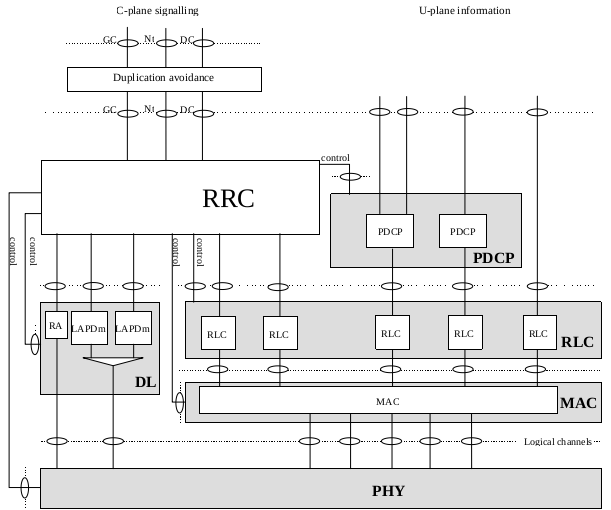
The following figure shows the channel mapping of logical channels, transport channels and physical channels:
R4 Channels
UMTS Channels
Logical Channel
According to section 4.3.2 Logical Channels of TS 25.321-4a0 Medium Access Control (MAC) protocol specification, the MAC layer defines the following logical channels:
| Logical Channels | Type | FDD/TDD | UL/DL | Plane |
|---|---|---|---|---|
| Broadcast Control Channel (BCCH) | Control | FDD/TDD | DL | C-plane |
| Paging Control Channel (PCCH) | Control | FDD/TDD | DL | C-plane |
| Common Control Channel (CCCH) | Control | FDD/TDD | UL/DL | C-plane |
| Dedicated Control Channel (DCCH) | Control | FDD/TDD | UL/DL | C-plane |
| Shared Channel Control Channel (SHCCH) | Control | TDD | UL/DL | C-plane |
| Common Traffic Channel (CTCH) | Traffic | FDD/TDD | UL/DL | U-plane |
| Dedicated Traffic Channel (DTCH) | Traffic | FDD/TDD | UL/DL | U-plane |
NOTE: The logical channels in R4 are the same with that in R99.
Transport Channel
According to section 5.2 Layer 1 Services and Functions of TS 25.301-440 Radio Interface Protocol Architecture, the Physical layer defines the following transport channels:
| Transport Channels | Type | FDD/TDD | UL/DL |
|---|---|---|---|
| Broadcast Channel (BCH) | Common | FDD/TDD | DL |
| Forward Access Channel (FACH) | Common | FDD/TDD | DL |
| Paging Channel (PCH) | Common | FDD/TDD | DL |
| Random Access Channel (RACH) | Common | FDD/TDD | UL |
| Common Packet Channel (CPCH) | Common | FDD | UL |
| Downlink Shared Channel (DSCH) | Common | TDD | DL |
| Uplink Shared Channel (USCH) | Common | TDD | UL |
| Dedicated Channel (DCH) | Dedicated | FDD/TDD | UL/DL |
NOTE: The transport channels in R4 are the same with that in R99.
Physical Channel
According to section 6 Mapping and association of physical channels of TS 25.211-460 Physical channels and mapping of transport channels onto physical channels (FDD), the Physical layer defines the following physical channels:
| Physical Channels | FDD/TDD | UL/DL | Reference |
|---|---|---|---|
| Primary Common Control Physical Channel (P-CCPCH) | FDD/TDD | DL | P-CCPCH |
| Secondary Common Control Physical Channel (S-CCPCH) | FDD/TDD | DL | S-CCPCH |
| Primary Synchronisation Channel (P-SCH) | FDD/TDD | DL | SCH |
| Secondary Synchronisation Channel (S-SCH) | FDD/TDD | DL | SCH |
| Physical Random Access Channel (PRACH) | FDD/TDD | UL | PRACH |
| Physical Common Packet Channel (PCPCH) | FDD | UL | |
| Primary Common Pilot Channel (P-CPICH) | FDD/TDD | DL | CPICH |
| Secondary Common Pilot Channel (S-CPICH) | FDD/TDD | DL | CPICH |
| Physical Downlink Shared Channel (PDSCH) | FDD/TDD | DL | |
| Acquisition Indicator Channel (AICH) | FDD/TDD | DL | AICH |
| Access Preamble Acquisition Indicator Channel (AP-AICH) | |||
| Paging Indicator Channel (PICH) | FDD/TDD | DL | PICH |
| CPCH Status Indicator Channel (CSICH) | |||
| Collision-Detection/Channel-Assignment Indicator Channel (CD/CA-ICH) | |||
| Dedicated Physical Data Channel (DPDCH) | FDD/TDD | DL/UL | DPDCH |
| Dedicated Physical Control Channel (DPCCH) | FDD/TDD | DL/UL | DPCCH |
NOTE: The physical channels in R4 are the same with that in R99.
Channel Mapping
The following figure shows the channel mapping of logical channels, transport channels and physical channels:
R5 Channels
UMTS Channels
Logical Channel
According to section 4.3.2 Logical Channels of TS 25.321-5e0 Medium Access Control (MAC) protocol specification, the MAC layer defines the following logical channels:
| Logical Channels | Type | FDD/TDD | UL/DL | Plane |
|---|---|---|---|---|
| Broadcast Control Channel (BCCH) | Control | FDD/TDD | DL | C-plane |
| Paging Control Channel (PCCH) | Control | FDD/TDD | DL | C-plane |
| Common Control Channel (CCCH) | Control | FDD/TDD | UL/DL | C-plane |
| Dedicated Control Channel (DCCH) | Control | FDD/TDD | UL/DL | C-plane |
| Shared Channel Control Channel (SHCCH) | Control | TDD | UL/DL | C-plane |
| Common Traffic Channel (CTCH) | Traffic | FDD/TDD | UL/DL | U-plane |
| Dedicated Traffic Channel (DTCH) | Traffic | FDD/TDD | UL/DL | U-plane |
NOTE: The logical channels in R5 are the same with that in R4.
Transport Channel
According to section 5.2 Layer 1 Services and Functions of TS 25.301-560 Radio Interface Protocol Architecture, the Physical layer defines the following transport channels:
| Transport Channels | Type | FDD/TDD | UL/DL |
|---|---|---|---|
| Broadcast Channel (BCH) | Common | FDD/TDD | DL |
| Forward Access Channel (FACH) | Common | FDD/TDD | DL |
| Paging Channel (PCH) | Common | FDD/TDD | DL |
| Random Access Channel (RACH) | Common | FDD/TDD | UL |
| Common Packet Channel (CPCH) | Common | FDD | UL |
| Downlink Shared Channel (DSCH) | Common | TDD | DL |
| Uplink Shared Channel (USCH) | Common | TDD | UL |
| High Speed Downlink Shared Channel (HS-DSCH) | Common | FDD/TDD | DL |
| Dedicated Channel (DCH) | Dedicated | FDD/TDD | UL/DL |
NOTE: The transport channel HS-DSCH is new added for HSDPA in R5.
Physical Channel
According to section 6 Mapping and association of physical channels of TS 25.211-580 Physical channels and mapping of transport channels onto physical channels (FDD), the Physical layer defines the following physical channels:
| Physical Channels | FDD/TDD | UL/DL |
|---|---|---|
| Primary Common Control Physical Channel (P-CCPCH) | FDD/TDD | DL |
| Secondary Common Control Physical Channel (S-CCPCH) | FDD/TDD | DL |
| Primary Synchronisation Channel (P-SCH) | FDD/TDD | DL |
| Secondary Synchronisation Channel (S-SCH) | FDD/TDD | DL |
| Acquisition Indicator Channel (AICH) | FDD/TDD | DL |
| Paging Indicator Channel (PICH) | FDD/TDD | DL |
| Physical Random Access Channel (PRACH) | FDD/TDD | UL |
| Primary Common Pilot Channel (P-CPICH) | FDD/TDD | DL |
| Secondary Common Pilot Channel (S-CPICH) | FDD/TDD | DL |
| Dedicated Physical Data Channel (DPDCH) | FDD/TDD | DL/UL |
| Dedicated Physical Control Channel (DPCCH) | FDD/TDD | DL/UL |
| High Speed Physical Downlink Shared Channel (HS-PDSCH) | FDD/TDD | DL |
| Shared Control Channel for HS-DSCH (HS-SCCH) | FDD/TDD | DL |
| Dedicated Physical Control Channel for HS-DSCH (HS-DPCCH) | FDD/TDD | UL |
NOTE1: The physical channels PDSCH, AP-AICH, CSICH and CD/CA-ICH are deleted from R5. NOTE2: The physical channels HS-PDSCH, HS-SCCH and HS-DPCCH are new added for HSDPA in R5.
Channel Mapping
The following figure shows the channel mapping of logical channels, transport channels and physical channels:
R6 Channels
Logical Channel
According to section 4.3.2 Logical Channels of TS 25.321-6i0 Medium Access Control (MAC) protocol specification, the MAC layer defines the following logical channels:
| Logical Channels | Type | FDD/TDD | UL/DL | Plane |
|---|---|---|---|---|
| Broadcast Control Channel (BCCH) | Control | FDD/TDD | DL | C-plane |
| Paging Control Channel (PCCH) | Control | FDD/TDD | DL | C-plane |
| Common Control Channel (CCCH) | Control | FDD/TDD | UL/DL | C-plane |
| Dedicated Control Channel (DCCH) | Control | FDD/TDD | UL/DL | C-plane |
| Shared Channel Control Channel (SHCCH) | Control | TDD | UL/DL | C-plane |
| MBMS point-to-multipoint Control Channel (MCCH) | Control | FDD/TDD | UL/DL | C-plane |
| MBMS point-to-multipoint Scheduling Channel (MSCH) | Control | FDD/TDD | UL/DL | C-plane |
| Common Traffic Channel (CTCH) | Traffic | FDD/TDD | UL/DL | U-plane |
| Dedicated Traffic Channel (DTCH) | Traffic | FDD/TDD | UL/DL | U-plane |
| MBMS point-to-multipoint Traffic Channel (MTCH) | Traffic | FDD/TDD | UL/DL | U-plane |
NOTE: The logical channels MCCH, MSCH and MTCH are new added for MBMS in R6.
Transport Channel
According to section 5.2 Layer 1 Services and Functions of TS 25.301-660 Radio Interface Protocol Architecture, the Physical layer defines the following transport channels:
| Transport Channels | Type | FDD/TDD | UL/DL |
|---|---|---|---|
| Broadcast Channel (BCH) | Common | FDD/TDD | DL |
| Forward Access Channel (FACH) | Common | FDD/TDD | DL |
| Paging Channel (PCH) | Common | FDD/TDD | DL |
| Random Access Channel (RACH) | Common | FDD/TDD | UL |
| Common Packet Channel (CPCH) | Common | FDD | UL |
| Downlink Shared Channel (DSCH) | Common | TDD | DL |
| Uplink Shared Channel (USCH) | Common | TDD | UL |
| High Speed Downlink Shared Channel (HS-DSCH) | Common | FDD/TDD | DL |
| Dedicated Channel (DCH) | Dedicated | FDD/TDD | UL/DL |
| Enhanced Dedicated Channel (E-DCH) | Dedicated | FDD/TDD | UL |
NOTE: The transport channel E-DCH is new added for HSUPA in R6.
Physical Channel
According to section 6 Mapping and association of physical channels of TS 25.211-6a0 Physical channels and mapping of transport channels onto physical channels (FDD), the Physical layer defines the following physical channels:
| Physical Channels | FDD/TDD | UL/DL |
|---|---|---|
| Primary Common Control Physical Channel (P-CCPCH) | FDD/TDD | DL |
| Secondary Common Control Physical Channel (S-CCPCH) | FDD/TDD | DL |
| Primary Synchronisation Channel (P-SCH) | FDD/TDD | DL |
| Secondary Synchronisation Channel (S-SCH) | FDD/TDD | DL |
| Acquisition Indicator Channel (AICH) | FDD/TDD | DL |
| Paging Indicator Channel (PICH) | FDD/TDD | DL |
| MBMS Indicator Channel (MICH) | FDD/TDD | DL |
| Physical Random Access Channel (PRACH) | FDD/TDD | UL |
| Primary Common Pilot Channel (P-CPICH) | FDD/TDD | DL |
| Secondary Common Pilot Channel (S-CPICH) | FDD/TDD | DL |
| High Speed Physical Downlink Shared Channel (HS-PDSCH) | FDD/TDD | DL |
| Shared Control Channel for HS-DSCH (HS-SCCH) | FDD/TDD | DL |
| Dedicated Physical Control Channel for HS-DSCH (HS-DPCCH) | FDD/TDD | UL |
| Dedicated Physical Data Channel (DPDCH) | FDD/TDD | DL/UL |
| Dedicated Physical Control Channel (DPCCH) | FDD/TDD | DL/UL |
| Fractional Dedicated Physical Channel (F-DPCH) | FDD/TDD | DL/UL |
| E-DCH Dedicated Physical Data Channel (E-DPDCH) | FDD/TDD | UL |
| E-DCH Dedicated Physical Control Channel (E-DPCCH) | FDD/TDD | UL |
| E-DCH Absolute Grant Channel (E-AGCH) | FDD/TDD | DL |
| E-DCH Relative Grant Channel (E-RGCH) | FDD/TDD | DL |
| E-DCH Hybrid ARQ Indicator Channel (E-HICH) | FDD/TDD | DL |
NOTE: The physical channels MICH, F-DPCH, E-DPDCH, E-DPCCH, E-AGCH, E-RGCH and E-HICH are new added for HSUPA and MBMS in R6.
Channel Mapping
The following figure shows the channel mapping of logical channels, transport channels and physical channels:
R7 Channels
UMTS Channels
Logical Channel
According to section 4.3.2 Logical Channels of TS 25.321-7j0 Medium Access Control (MAC) protocol specification, the MAC layer defines the following logical channels:
| Logical Channels | Type | FDD/TDD | UL/DL | Plane |
|---|---|---|---|---|
| Broadcast Control Channel (BCCH) | Control | FDD/TDD | DL | C-plane |
| Paging Control Channel (PCCH) | Control | FDD/TDD | DL | C-plane |
| Common Control Channel (CCCH) | Control | FDD/TDD | UL/DL | C-plane |
| Dedicated Control Channel (DCCH) | Control | FDD/TDD | UL/DL | C-plane |
| Shared Channel Control Channel (SHCCH) | Control | TDD | UL/DL | C-plane |
| MBMS point-to-multipoint Control Channel (MCCH) | Control | FDD/TDD | UL/DL | C-plane |
| MBMS point-to-multipoint Scheduling Channel (MSCH) | Control | FDD/TDD | UL/DL | C-plane |
| Common Traffic Channel (CTCH) | Traffic | FDD/TDD | UL/DL | U-plane |
| Dedicated Traffic Channel (DTCH) | Traffic | FDD/TDD | UL/DL | U-plane |
| MBMS point-to-multipoint Traffic Channel (MTCH) | Traffic | FDD/TDD | UL/DL | U-plane |
NOTE: The logical channels in R7 are the same with that in R6.
Transport Channel
According to section 5.2 Layer 1 Services and Functions of TS 25.301-750 Radio Interface Protocol Architecture, the Physical layer defines the following transport channels:
| Transport Channels | Type | FDD/TDD | UL/DL |
|---|---|---|---|
| Broadcast Channel (BCH) | Common | FDD/TDD | DL |
| Forward Access Channel (FACH) | Common | FDD/TDD | DL |
| Paging Channel (PCH) | Common | FDD/TDD | DL |
| Random Access Channel (RACH) | Common | FDD/TDD | UL |
| Common Packet Channel (CPCH) | Common | FDD | UL |
| Downlink Shared Channel (DSCH) | Common | TDD | DL |
| Uplink Shared Channel (USCH) | Common | TDD | UL |
| High Speed Downlink Shared Channel (HS-DSCH) | Common | FDD/TDD | DL |
| Dedicated Channel (DCH) | Dedicated | FDD/TDD | UL/DL |
| Enhanced Dedicated Channel (E-DCH) | Dedicated | FDD/TDD | UL |
NOTE: The transport channels in R7 are the same with that in R6.
Physical Channel
According to section 6 Mapping and association of physical channels of TS 25.211-7a0 Physical channels and mapping of transport channels onto physical channels (FDD), the Physical layer defines the following physical channels:
| Physical Channels | FDD/TDD | UL/DL |
|---|---|---|
| Primary Common Control Physical Channel (P-CCPCH) | FDD/TDD | DL |
| Secondary Common Control Physical Channel (S-CCPCH) | FDD/TDD | DL |
| Primary Synchronisation Channel (P-SCH) | FDD/TDD | DL |
| Secondary Synchronisation Channel (S-SCH) | FDD/TDD | DL |
| Acquisition Indicator Channel (AICH) | FDD/TDD | DL |
| Paging Indicator Channel (PICH) | FDD/TDD | DL |
| MBMS Indicator Channel (MICH) | FDD/TDD | DL |
| Physical Random Access Channel (PRACH) | FDD/TDD | UL |
| Primary Common Pilot Channel (P-CPICH) | FDD/TDD | DL |
| Secondary Common Pilot Channel (S-CPICH) | FDD/TDD | DL |
| High Speed Physical Downlink Shared Channel (HS-PDSCH) | FDD/TDD | DL |
| Shared Control Channel for HS-DSCH (HS-SCCH) | FDD/TDD | DL |
| Dedicated Physical Control Channel for HS-DSCH (HS-DPCCH) | FDD/TDD | UL |
| Dedicated Physical Data Channel (DPDCH) | FDD/TDD | DL/UL |
| Dedicated Physical Control Channel (DPCCH) | FDD/TDD | DL/UL |
| Fractional Dedicated Physical Channel (F-DPCH) | FDD/TDD | DL/UL |
| E-DCH Dedicated Physical Data Channel (E-DPDCH) | FDD/TDD | UL |
| E-DCH Dedicated Physical Control Channel (E-DPCCH) | FDD/TDD | UL |
| E-DCH Absolute Grant Channel (E-AGCH) | FDD/TDD | DL |
| E-DCH Relative Grant Channel (E-RGCH) | FDD/TDD | DL |
| E-DCH Hybrid ARQ Indicator Channel (E-HICH) | FDD/TDD | DL |
NOTE: The physical channels in R7 are the same with that in R6.
Channel Mapping
The following figure shows the channel mapping of logical channels, transport channels and physical channels:
R8 Channels
UMTS Channels
Logical Channel
According to section 4.3.2 Logical Channels of TS 25.321-8g0 Medium Access Control (MAC) protocol specification, the MAC layer defines the following logical channels:
| Logical Channels | Type | FDD/TDD | UL/DL | Plane |
|---|---|---|---|---|
| Broadcast Control Channel (BCCH) | Control | FDD/TDD | DL | C-plane |
| Paging Control Channel (PCCH) | Control | FDD/TDD | DL | C-plane |
| Common Control Channel (CCCH) | Control | FDD/TDD | UL/DL | C-plane |
| Dedicated Control Channel (DCCH) | Control | FDD/TDD | UL/DL | C-plane |
| Shared Channel Control Channel (SHCCH) | Control | TDD | UL/DL | C-plane |
| MBMS point-to-multipoint Control Channel (MCCH) | Control | FDD/TDD | UL/DL | C-plane |
| MBMS point-to-multipoint Scheduling Channel (MSCH) | Control | FDD/TDD | UL/DL | C-plane |
| Common Traffic Channel (CTCH) | Traffic | FDD/TDD | UL/DL | U-plane |
| Dedicated Traffic Channel (DTCH) | Traffic | FDD/TDD | UL/DL | U-plane |
| MBMS point-to-multipoint Traffic Channel (MTCH) | Traffic | FDD/TDD | UL/DL | U-plane |
NOTE: The logical channels in R8 are the same with that in R7.
Transport Channel
According to section 5.2 Layer 1 Services and Functions of TS 25.301-750 Radio Interface Protocol Architecture, the Physical layer defines the following transport channels:
| Transport Channels | Type | FDD/TDD | UL/DL |
|---|---|---|---|
| Broadcast Channel (BCH) | Common | FDD/TDD | DL |
| Forward Access Channel (FACH) | Common | FDD/TDD | DL |
| Paging Channel (PCH) | Common | FDD/TDD | DL |
| Random Access Channel (RACH) | Common | FDD/TDD | UL |
| Downlink Shared Channel (DSCH) | Common | TDD | DL |
| Uplink Shared Channel (USCH) | Common | TDD | UL |
| High Speed Downlink Shared Channel (HS-DSCH) | Common | FDD/TDD | DL |
| Enhanced Dedicated Channel (E-DCH) | Common [NOTE1] |
FDD/1.28 Mcps TDD | UL |
| Dedicated Channel (DCH) | Dedicated | FDD/TDD | UL/DL |
| Enhanced Dedicated Channel (E-DCH) | Dedicated [NOTE2] |
FDD/TDD | UL |
[NOTE1] RRC state: CELL_FACH state, IDLE mode [NOTE2] RRC state: CELL_DCH
NOTE: The transport channel E-DCH (Common type) is the new added in R8.
Physical Channel
According to section 6 Mapping and association of physical channels of TS 25.211-870 Physical channels and mapping of transport channels onto physical channels (FDD), the Physical layer defines the following physical channels:
| Physical Channels | FDD/TDD | UL/DL |
|---|---|---|
| Primary Common Control Physical Channel (P-CCPCH) | FDD/TDD | DL |
| Secondary Common Control Physical Channel (S-CCPCH) | FDD/TDD | DL |
| Primary Synchronisation Channel (P-SCH) | FDD/TDD | DL |
| Secondary Synchronisation Channel (S-SCH) | FDD/TDD | DL |
| Acquisition Indicator Channel (AICH) | FDD/TDD | DL |
| Paging Indicator Channel (PICH) | FDD/TDD | DL |
| MBMS Indicator Channel (MICH) | FDD/TDD | DL |
| Physical Random Access Channel (PRACH) | FDD/TDD | UL |
| Primary Common Pilot Channel (P-CPICH) | FDD/TDD | DL |
| Secondary Common Pilot Channel (S-CPICH) | FDD/TDD | DL |
| High Speed Physical Downlink Shared Channel (HS-PDSCH) | FDD/TDD | DL |
| Shared Control Channel for HS-DSCH (HS-SCCH) | FDD/TDD | DL |
| Dedicated Physical Control Channel for HS-DSCH (HS-DPCCH) | FDD/TDD | UL |
| Dedicated Physical Data Channel (DPDCH) | FDD/TDD | DL/UL |
| Dedicated Physical Control Channel (DPCCH) | FDD/TDD | DL/UL |
| Fractional Dedicated Physical Channel (F-DPCH) | FDD/TDD | DL/UL |
| E-DCH Dedicated Physical Data Channel (E-DPDCH) | FDD/TDD | UL |
| E-DCH Dedicated Physical Control Channel (E-DPCCH) | FDD/TDD | UL |
| E-DCH Absolute Grant Channel (E-AGCH) | FDD/TDD | DL |
| E-DCH Relative Grant Channel (E-RGCH) | FDD/TDD | DL |
| E-DCH Hybrid ARQ Indicator Channel (E-HICH) | FDD/TDD | DL |
NOTE: The physical channels in R8 are the same with that in R7.
Channel Mapping
The following figure shows the channel mapping of logical channels, transport channels and physical channels:
Mobile Station (MS)
The MT plus any TE constitutes the Mobile Station (MS). That’s: MS = MT + TE.
The following figure is Figure 1: PLMN Access Reference Configuration (in A/Gb mode and GERAN Iu mode) from TS 24.002-810 PLMN Access Reference Configuration:
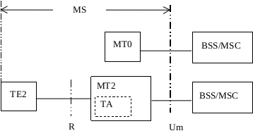
There are two types of MT:
- MT0 includes functions belonging to the functional group MT, with support of no terminal interfaces.
-
MT2 includes functions belonging to the functional group MT, and with an interface that complies with the 3GPP TS 27.00z series Terminal Adaptation Function specifications. Accordingly, the interchange circuit mapping at the MT2 to TE interface shall comply with the ITU-T V.24 recommendation; while the physical implementation shall conform either to the ITU-T V.28, or to the IrDA IrPHY Physical signalling standard specification, or to the PCMCIA 2.1, or to the PC-Card 3.0, electrical specification or to later revisions.
- TS 27.001 - General on Terminal Adaptation Functions (TAF) for Mobile Stations (MS)
- TS 27.002 - Terminal Adaptation Functions (TAF) for services using asynchronous bearer capabilities
-
TS 27.003 - Terminal Adaptation Functions (TAF) for services using synchronous bearer capabilities
- ITU-T Recommendation V.24 (1996) - List of definitions for interchange circuits between data terminal equipment (DTE) and data circuit terminating equipment (DCE)”
- ITU T Recommendation V.28 (1993) - Electrical characteristics for unbalanced double current interchange circuits
- Infrared Data Association IrDA - IrPHY Physical layer signalling standard
- Personal Computer Memory Card Association - PCMCIA 2.1 or PC Card 3.0 electrical specification or later revisions
The Mobile Station (MS) related standards include:
- TS 24.002 - PLMN Access Reference Configuration
GSM Radio Access Network (GERAN)
GERAN = BSC (Base Station Controller) + BTS (Base Transceiver Station)
Overview
- TS 43.051 - GSM/EDGE Radio Access Network (GERAN); Overall Description - Stage 2
Radio Interface (Um)
The following figure is Figure 3: Assumed GERAN Model from TS 43.051-400 GSM/EDGE Radio Access Network (GERAN); Overall Description - Stage 2:
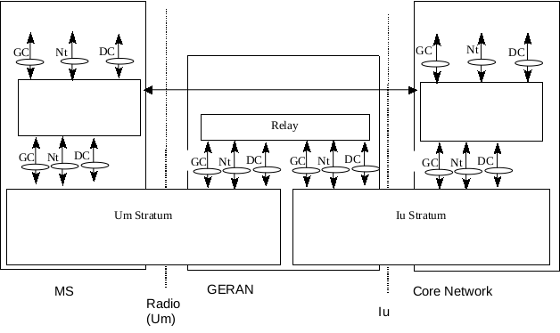
The following figure is Figure 10: Radio Interface protocol architecture from TS 43.051-400 GSM/EDGE Radio Access Network (GERAN); Overall Description - Stage 2:
- TS 45.001 - GERAN Physical layer on the radio path - General description
- TS 45.002 - Multiplexing and multiple access on the radio path
- TS 45.003 - Channel coding
- TS 45.004 - Modulation
-
TS 45.005 - Radio transmission and reception
- TS 45.008 - Radio subsystem link control
- TS 45.009 - Link adaptation
- TS 45.010 - Radio subsystem synchronization
- TS 45.015 - Downlink Advanced Receiver Performance (DARP); Implementation guidelines
- TS 45.022 - Radio link management in hierarchical networks
- TS 45.050 - Background for Radio Frequency (RF) requirements
-
TS 45.056 - GSM Cordless Telephony System (CTS), Phase 1; CTS-FP Radio subsystem
- TR 45.902 - Flexible Layer One (FLO)
- TR 45.903 - Feasibility Study on Single Antenna Interference Cancellation (SAIC) for GSM networks
- TR 45.912 - Feasibility study for evolved GSM/EDGE Radio Access Network (GERAN)
- TR 45.913 - Optimized transmit pulse shape for downlink Enhanced General Packet Radio Service (EGPRS2-B)
- TR 45.914 - Circuit Switched Voice Capacity Evolution for GSM/EDGE Radio Access Network (GERAN)
Abis Interface
- TS 48.051 - BSC-BTS interface General aspects
- TS 48.052 - BSC-BTS Interface Principles
- TS 48.054 - BSC-BTS Layer 1 Specification
- TS 48.056 - BSC-BTS Layer 2 Specification
- TS 48.058 - BSC-BTS Layer 3 Specification
- TS 48.060 - Inband Control of Remote Transcoders and Rate Adaptors
- TS 48.061 - Inband Control of Remote Transcoders and Rate Adaptors for Half Rate Traffic Channels
A Interface
- TS 48.001 - BSS-MSC interface General aspects
- TS 48.002 - BSS-MSC interface Interface principles
- TS 48.004 - BSS-MSC interface Layer 1 specification
- TS 48.006 - Signalling transport mechanism specification for the BSS-MSC interface
- TS 48.008 - MSC-BSS interface Layer 3 specification
Gb Interface
- TS 48.016 - BSS-SGSN interface Network Service
- TS 48.018 - BSS-SGSN BSS GPRS Protocol (BSSGP)
GSM Core Network (MAP)
MAP for GSM (prior to Release 4) is specified by 3GPP TS 09.02 (MAP v1, MAP v2).
GSM Technical Details
The following GSM technical detail is from GSM Tutorial.
Modulation
Modulation is the process of transforming the input data into a suitable format for the transmission medium. The transmitted data is demodulated back to its original form at the receiving end. The GSM uses Gaussian Minimum Shift Keying (GMSK) modulation method. Refer to 3GPP TS 45.004 Modulation.
Access Methods
Radio spectrum being a limited resource that is consumed and divided among all the users, GSM devised a combination of TDMA/FDMA as the method to divide the bandwidth among the users. In this process, the FDMA part divides the frequency of the total 25 MHz bandwidth into 124 carrier frequencies of 200 kHz bandwidth.
Each BS is assigned with one or multiple frequencies, and each of this frequency is divided into eight timeslots using a TDMA scheme. Each of these slots are used for both transmission as well as reception of data. These slots are separated by time so that a mobile unit doesn’t transmit and receive data at the same time.
Refer to 3GPP TS 45.002 Multiplexing and multiple access on the radio path.
Transmission Rate
The total symbol rate for GSM at 1 bit per symbol in GMSK produces 270.833 K symbols/second. The gross transmission rate of a timeslot is 22.8 Kbps.
GSM is a digital system with an over-the-air bit rate of 270 kbps.
Frequency Band
The uplink frequency range specified for GSM is 933 - 960 MHz (basic 900 MHz band only). The downlink frequency band 890 - 915 MHz (basic 900 MHz band only). Refer to 3GPP TS 45.005 Radio transmission and reception.
Channel Spacing
Channel spacing indicates the spacing between adjacent carrier frequencies. For GSM, it is 200 kHz. Refer to 3GPP TS 45.005 Radio transmission and reception.
Duplex Distance
Duplex distance is the space between the uplink and downlink frequencies. The duplex distance for GSM is 80 MHz, where each channel has two frequencies that are 80 MHz apart. Refer to TS 45.005 Radio transmission and reception.
Speech Coding
For speech coding or processing, GSM uses Linear Predictive Coding (LPC). This tool compresses the bit rate and gives an estimate of the speech parameters. When the audio signal passes through a filter, it mimics the vocal tract. Here, the speech is encoded at 13 kbps.
GSM Services
GSM, LTE, UMTS and IMS Call Flows
GSM offers three basic types of services:
- Telephony services or teleservices
- Data services or bearer services
- Supplementary services
Procedures
- TS 43.022 - Functions related to Mobile Station in idle mode and group receive mode
GPRS (2.5G)
General Packet Radio Service (GPRS) is a packet oriented mobile data service on the 2G and 3G cellular communication system’s Global System for Mobile Communications (GSM). GPRS was originally standardized by European Telecommunications Standards Institute (ETSI) in response to the earlier Cellular Digital Packet Data (CDPD) and i-mode packet-switched cellular technologies. It is now maintained by the 3rd Generation Partnership Project (3GPP).
GPRS is a best-effort service, implying variable throughput and latency that depend on the number of other users sharing the service concurrently, as opposed to circuit switching, where a certain Quality of Service (QoS) is guaranteed during the connection. In 2G systems, GPRS provides data rates of 56–114 kbit/second. 2G cellular technology combined with GPRS is sometimes described as 2.5G, that is, a technology between the second (2G) and third (3G) generations of mobile telephony. It provides moderate-speed data transfer, by using unused Time Division Multiple Access (TDMA) channels in, for example, the GSM system. GPRS is integrated into GSM Release 97 and newer releases.
Based on specifications in Release 97, GPRS typically reached speeds of 40Kbps in the downlink and 14Kbps in the uplink by aggregating GSM time slots into one bearer. Enhancements in R98 and R99 meant that GPRS could theoretically reach downlink speeds of up to 171Kbps.
| Phase 1 | Phase 2 | Phase 3 |
|---|---|---|
| 02.60业务描述 | 03.60 系统描述和网络结构 | 04.60 RLC/MAC协议 |
| 03.64 无线接口描述 | 04.61 PTM-M业务 | |
| 03.61 点对多点-广播业务 | 04.62 PTM-G业务 | |
| 03.62 点对多点-群呼 | 04.64 LLC04.65SNDCP | |
| 07.60 用户互通 | ||
| 08.14 Gb层1 | ||
| 08.16 Gb层网络业务 | ||
| 08.18 BSSGP、Gb接口 | ||
| 09.16 Gb层2 | ||
| 09.18 Gb层3 | ||
| 09.60 Gn&Gp接口 | ||
| 09.61 外部网路互通 |
EDGE / EGPRS (2.75G)
Enhanced Data rates for GSM Evolution (EDGE), also known as Enhanced GPRS (EGPRS), is a digital mobile phone technology that allows improved data transmission rates as a backward-compatible extension of GSM. EDGE is considered a pre-3G radio technology and is part of ITU’s 3G definition. EDGE was deployed on GSM networks beginning in 2003 - initially by Cingular (now AT&T) in the United States.
EDGE is standardized also by 3GPP as part of the GSM family, which is introduced into Release 98. A variant, so called Compact-EDGE, was developed for use in a portion of Digital AMPS (D-AMPS) network spectrum.
Through the introduction of sophisticated methods of coding and transmitting data, EDGE delivers higher bit-rates per radio channel, resulting in a threefold increase in capacity and performance compared with an ordinary GSM/GPRS connection.
EDGE can be used for any packet switched application, such as an Internet connection.
Reading should start with the 44 series and 45 series of the 3GPP specifications.
Evolved EDGE
Evolved EDGE continues in Release 7 of the 3GPP standard providing reduced latency and more than doubled performance e.g. to complement High-Speed Packet Access (HSPA). Peak bit-rates of up to 1 Mbit/s and typical bit-rates of 400 kbit/s can be expected.
Evolved EDGE improves on EDGE in a number of ways. Latencies are reduced by lowering the Transmission Time Interval by half (from 20 ms to 10 ms). Bit rates are increased up to 1 Mbit/s peak bandwidth and latencies down to 80 ms using dual carrier, higher symbol rate and higher-order modulation (32QAM and 16QAM instead of 8PSK), and turbo codes to improve error correction. And finally signal quality is improved using dual antennas improving average bit-rates and spectrum efficiency. EDGE Evolution can be gradually introduced as software upgrades, taking advantage of the installed base. With EDGE Evolution, end-users will be able to experience mobile internet connections corresponding to a 500 kbit/s ADSL service.
EDGE Evolution has:
- Improved spectral efficiency with reduced latencies down to 100ms;
- Increased throughput speeds to 1.3Mbps in the downlink and 653Kbps in the uplink.