I²C: Inter-Integrated Circuit
This article introduces the I²C (Inter-Integrated Circuit).
Overview
I²C (Inter-Integrated Circuit) is a multi-master, multi-slave, single-ended, serial computer bus invented by Philips Semiconductor (now NXP Semiconductors). It is typically used for attaching lower-speed peripheral ICs to processors and microcontrollers in short-distance, intra-board communication. Alternatively, I²C is spelled I2C or IIC.
Since October 10, 2006, no licensing fees are required to implement the I²C protocol. However, fees are still required to obtain I²C slave addresses allocated by NXP Semiconductors.
SMBus, defined by Intel in 1995, is a subset of I²C that defines the protocol use more strictly. One purpose of SMBus is to promote robustness and interoperability. Accordingly, modern I²C systems incorporate some policies and rules from SMBus, sometimes supporting both I²C and SMBus, requiring only minimal reconfiguration either by commanding or output pin use.
I²C Specification
The history of I²C specification releases:
- In 1982, the original 100 kHz I²C system was created as a simple internal bus system for building control electronics with various Philips chips.
- In 1992, Version 1 added 400 kHz Fast-mode (Fm) and a 10-bit addressing mode to increase capacity to 1008 nodes. This was the first standardized version.
- In 1998, Version 2 added 3.4 MHz High-speed mode (Hs) with power-saving requirements for electric voltage and current.
- In 2000, Version 2.1 introduced a minor cleanup of version 2.
- In 2007, Version 3 added 1 MHz Fast-mode plus (Fm+), and a device ID mechanism.
- In 2012, Version 4 added 5 MHz Ultra Fast-mode (UFm) for new USDA and USCL lines using push-pull logic without pull-up resistors, and added assigned manufacturer ID table.
- In 2012, Version 5 corrected mistakes.
- In 2014, Version 6 corrected two graphs. This is the most recent standard. Refer to Official I²C Specification Version 6.
Architecture
I²C uses only two bidirectional open-drain lines, Serial Data Line (SDA) and Serial Clock Line (SCL), pulled up with resistors. Typical voltages used are +5 V or +3.3 V although systems with other voltages are permitted.
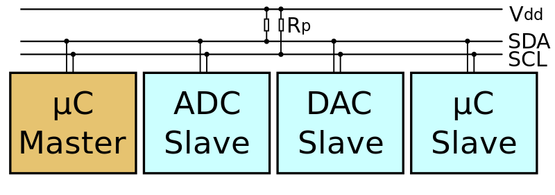
The I²C reference design has a 7-bit or a 10-bit (depending on the device used) address space. Common I²C bus speeds are the 100 kbit/s standard mode and the 10 kbit/s low-speed mode, but arbitrarily low clock frequencies are also allowed. Recent revisions of I²C can host more nodes and run at faster speeds (400 kbit/s Fast mode, 1 Mbit/s Fast mode plus or Fm+, and 3.4 Mbit/s High Speed mode). These speeds are more widely used on embedded systems than on PCs. There are also other features, such as 16-bit addressing.
The maximum number of nodes is limited by the address space, and also by the total bus capacitance of 400 pF, which restricts practical communication distances to a few meters. The relatively high impedance and low noise immunity requires a common ground potential, which again restricts practical use to communication within the same PC board or small system of boards.
Operation
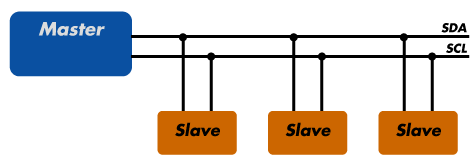
The reference design is a bus with a serial clock (SCL) and serial data (SDA) lines with 7-bit addressing. The bus has two roles for nodes:
- Master node: node that generates the clock and initiates communication with slaves.
- Slave node: node that receives the clock and responds when addressed by the master.
The bus is a multi-master bus which means any number of master nodes can be present. Additionally, master and slave roles may be changed between messages (after a STOP is sent).
There may be four potential modes of operation for a given bus device, although most devices only use a single role and its two modes:
- master transmit: master node is sending data to a slave
- master receive: master node is receiving data from a slave
- slave transmit: slave node is sending data to the master
- slave receive: slave node is receiving data from the master
The master is initially in master transmit mode by sending a START bit followed by the 7-bit address of the slave it wishes to communicate with, which is finally followed by a single bit representing whether it wishes to write (0) to or read (1) from the slave.
If the slave exists on the bus then it will respond with an ACK bit (active low for acknowledged) for that address. The master then continues in either transmit or receive mode (according to the read/write bit it sent), and the slave continues in its complementary mode (receive or transmit, respectively).
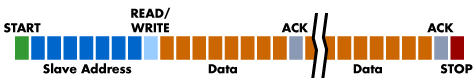
The address and the data bytes are sent most significant bit first. The START bit is indicated by a high-to-low transition of SDA with SCL high; the STOP bit is indicated by a low-to-high transition of SDA with SCL high. All other transitions of SDA take place with SCL low.
If the master wishes to write to the slave then it repeatedly sends a byte with the slave sending an ACK bit. (In this situation, the master is in master transmit mode and the slave is in slave receive mode)
If the master wishes to read from the slave then it repeatedly receives a byte from the slave, the master sending an ACK bit after every byte but the last one. (In this situation, the master is in master receive mode and the slave is in slave transmit mode)
The master then either ends transmission with a stop bit, or it may send another START bit if it wishes to retain control of the bus for another transfer (a combined message).
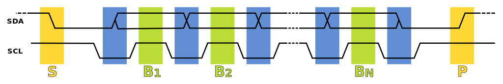
- Data transfer is initiated with a START bit (S) signaled by SDA being pulled low while SCL stays high.
- SDA sets the 1st data bit level while keeping SCL low (during blue bar time.)
- The data is sampled (received) when SCL rises (green) for the first bit (B1).
- This process repeats, SDA transitioning while SCL is low, and the data being read while SCL is high (B2, Bn).
- A STOP bit (P) is signaled when SDA is pulled high while SCL is high.
Message Protocols
In order to avoid false marker detection, SDA is changed on the SCL falling edge and is sampled and captured on the rising edge of SCL.
I²C defines basic types of messages, each of which begins with a START and ends with a STOP:
- Single message where a master writes data to a slave;
- Single message where a master reads data from a slave;
- Combined messages, where a master issues at least two reads and/or writes to one or more slaves.
In a combined message, each read or write begins with a START and the slave address. After the first START in a combined message these are also called repeated START bits. Repeated START bits are not preceded by STOP bits, which is how slaves know the next transfer is part of the same message.
References
- List of network buses
- I²C wikipedia
- I²C Tutorial or PDF version
- I²C Specification Version 6 or PDF version
- How I2C Communication Works
- Introduction to I²C and SPI protocols
- I2C Serial Machine Interface
- Using the I2C Bus