Telecom: LTE/LTE-Advanced
This article introduce the LTE/LTE-Advanced defined by 3GPP.
History
Although marketed as a 4G wireless service, LTE (as specified in the 3GPP Release 8 and 9 document series) does not satisfy the technical requirements the 3GPP consortium has adopted for its new LTE-Advanced standard. The requirements were originally set forth by the ITU-R organization in its IMT Advanced specification. However, due to marketing pressures and the significant advancements that WiMAX, Evolved High Speed Packet Access (HSPA+) and LTE bring to the original 3G technologies, ITU later decided that LTE together with the aforementioned technologies can be called 4G technologies. The LTE Advanced standard formally satisfies the ITU-R requirements to be considered IMT-Advanced. To differentiate LTE Advanced and WiMAX-Advanced from current 4G technologies, ITU has defined them as True 4G.
Standards
ITU Recommendations related to LTE/LTE-Advanced are introduced in IMT-Advanced (4G).
LTE/LTE-Advanced related Technical Specifications (TS) and Technical Reports (TR) are:
- TD RP-040461 Proposed Study Item on Evolved UTRA and UTRAN => 发起LTE可行性研究项目的决议 (2004.12)
- REV-090022 3GPP IMT-Advanced Evaluation Workshop Other considerations
- 2009_10_3GPP_IMT Proposal for Candidate Radio Interface Technologies for IMT-Advanced Based on LTE Release 10 and Beyond (LTE‐Advanced)
- TR 25.913-800 Requirements for E-UTRA and E-UTRAN => LTE系统需求报告
- TR 25.913-900 Requirements for Evolved UTRA (E-UTRA) and Evolved UTRAN (E-UTRAN) => LTE系统需求报告
- TR 36.913-801 Requirements for further advancements for E-UTRA (LTE-Advanced) => LTE-Advanced系统需求报告
- TR 36.913-a00 Requirements for further advancements for E-UTRA (LTE-Advanced) => LTE-Advanced系统需求报告
- TR 25.912-800 Feasibility study for evolved UTRA and UTRAN => LTE可行性研究
- TR 36.912-a00 Feasibility study for Further Advancements for E-UTRA (LTE-Advanced) => LTE-Advanced可行性研究
- TR 25.813-710 E-UTRA and E-UTRAN - Radio interface protocol aspects => LTE无线接口协议
- TR 25.814-710 Physical layer aspects for E-UTRA => LTE物理层
- TR 36.814-900 Further advancements for E-UTRA physical layer aspects => LTE-Advanced物理层
- TR 36.815-910 Further advancements for E-UTRA - LTE-Advanced feasibility studies in RAN WG4
- TS 22.278-8a0 Service requirements for the Evolved Packet System (EPS) => EPS需求报告
- TS 36.300-8c0 E-UTRA Overall description – Stage 2 => E-UTRA整体描述
Specifications: TS 36.xxx
Requirements
The objective of Evolved UTRA and UTRAN is to develop a framework for the evolution of the 3GPP radio-access technology towards a high-data-rate, low-latency and packet-optimized radio-access technology.
The LTE/LTE-Advanced requirements are defined in TR 25.913-800 Requirements for E-UTRA and E-UTRAN:
-
Peak data rate
Configuration: 1 transmit antenna and 2 receive antennas at UE
Downlink: instantaneous downlink peak data rate of 100Mb/s within a 20 MHz downlink spectrum allocation (5 bps/Hz)
Uplink: instantaneous uplink peak data rate of 50Mb/s (2.5 bps/Hz) within a 20MHz uplink spectrum allocation.
-
C-plane latency
Transition time (excluding downlink paging delay and NAS signalling delay) of less than 100 ms from a camped-state (such as Release 6 Idle Mode) to an active state (such as Release 6 CELL_DCH).
Transition time (excluding DRX interval) of less than 50 ms between a dormant state (such as Release 6 CELL_PCH) and an active state (such as Release 6 CELL_DCH).
-
C-plane capacity
At least 200 users per cell should be supported in the active state for spectrum allocations up to 5 MHz, and at least 400 users for higher spectrum allocation.
-
U-plane latency
Less than 5 ms in unload condition (i.e. single user with single data stream) for small IP packet.
-
User throughput
Downlink: User throughput per MHz, 2 to 3 times Release 6 HSDPA. Averaged user throughput per MHz, 3 to 4 times Release 6 HSDPA.
Uplink: User throughput per MHz, 2 to 3 times Release 6 Enhanced Uplink. Averaged user throughput per MHz, 2 to 3 times Release 6 Enhanced Uplink.
-
Spectrum efficiency
Downlink: In a loaded network, target for spectrum efficiency (bits/sec/Hz/site), 3 to 4 times Release 6 HSDPA.
Uplink: In a loaded network, target for spectrum efficiency (bits/sec/Hz/site), 2 to 3 times Release 6 Enhanced Uplink.
-
Mobility
E-UTRAN should be optimized for low mobile speed from 0 to 15 km/h. Higher mobile speed between 15 and 120 km/h should be supported with high performance.
Mobility across the cellular network shall be maintained at speeds from 120 km/h to 350 km/h (or even up to 500 km/h depending on the frequency band).
-
Coverage
User throughput, spectrum efficiency and mobility targets above should be met for 5 km cells, and with a slight degradation for 30 km cells. Cells range up to 100 km should not be precluded.
-
Further Enhanced MBMS
E-UTRA broadcast transmission should use the same fundamental modulation, coding and multiple access whether it is deployed on dedicated carrier or a carrier shared with unicast.
-
Deployment Scenarios
E-UTRAN shall support the following two deployment scenarios at least:
- Standalone deployment scenario
- Integrating with existing UTRAN and/or GERAN deployment scenario
-
Spectrum flexibility
E-UTRA shall operate in spectrum allocations of different sizes, including 1.25 MHz, 1.6MHz, 2.5 MHz, 5 MHz, 10 MHz, 15 MHz and 20 MHz in both the uplink and downlink. Operation in paired and unpaired spectrum shall be supported.
The system shall be able to support (same and different) content delivery over an aggregation of resources including Radio Band Resources (as well as power, adaptive scheduling, etc) in the same and different bands, in both uplink and downlink and in both adjacent and non-adjacent channel arrangements.
-
Spectrum deployment
E-UTRA is required to cope with following scenarios:
- Co-existence in the same geographical area and co-location with GERAN/UTRAN on adjacent channels.
- Co-existence in the same geographical area and co-location between operators on adjacent channels.
- Co-existence on overlapping and/or adjacent spectrum at country borders.
- E-UTRA shall be possible to operate standalone, i.e. there is no need for any other carrier to be available.
- All frequency bands should be allowed following release independent frequency band principles.
-
Co-existence and interworking with 3GPP RAT
The following requirements are applicable to inter-working between E-UTRA and other 3GPP systems:
- E-UTRAN Terminals supporting also UTRAN and/or GERAN operation should be able to support measurement of, and handover from and to, both 3GPP UTRA and 3GPP GERAN systems correspondingly with acceptable impact on terminal complexity and network performance.
- E-UTRAN is required to efficiently support inter-RAT measurements with acceptable impact on terminal complexity and network performance, by e.g. providing UE’s with measurement opportunities through downlink and uplink scheduling.
- The interruption time during a handover of real-time services between E-UTRAN and UTRAN is less than 300 msec.
- The interruption time during a handover of non real-time services between E-UTRAN and UTRAN should be less than 500 msec.
- The interruption time during a handover of real-time services between E-UTRAN and GERAN is less than 300 msec.
- The interruption time during a handover of non real-time services between E-UTRAN and GERAN should be less than 500 msec.
- Non-active terminals (such as one being in Release 6 idle mode or CELL_PCH) which support UTRAN and/or GERAN in addition to E-UTRAN shall not need to monitor paging messages only from one of GERAN, UTRA or E-UTRA.
-
Requirements for E-UTRAN architecture and migration
- A single E-UTRAN architecture should be agreed.
- The E-UTRAN architecture shall be packet based, although provision should be made to support systems supporting real-time and conversational class traffic.
- E-UTRAN architecture shall minimize the presence of single points of failure where possible without additional cost for backhaul.
- E-UTRAN architecture shall simplify and minimize the introduced number of interfaces where possible.
- Radio Network Layer (RNL) and Transport Network Layer (TNL) interaction should not be precluded if in the interest of improved system performance.
- E-UTRAN architecture shall support an end-to-end QoS. The Transport Network Layer (TNL) shall provide the appropriate QoS requested by the Radio Network Layer (RNL).
- QoS mechanism(s) shall take into account the various types of traffic that exists to provide efficient bandwidth utilization: Control Plane traffic, User Plane traffic, O&M traffic etc.
- The E-UTRAN shall be designed in such a way to minimize the delay variation (jitter) for e.g. TCP/IP for packet communication.
-
Radio Resource Management requirements
- Enhanced support for end to end QoS
- Efficient support for transmission of higher layers
- Support of load sharing and policy management across different Radio Access Technologies
-
Complexity requirements for overall system
- Minimize the number of options.
- No redundant mandatory features.
- Reduce the number of necessary test cases, e.g. Reduce the number of states of protocols, minimize the number of procedures, appropriate parameter range and granularity.
-
Complexity requirements for UE
- UE complexity in terms of supporting multi-RAT (GERAN/UTRA/E-UTRA) should be considered when considering the complexity of E-UTRA features.
- The mandatory features shall be kept to the minimum.
- There shall be no redundant or duplicate specifications of mandatory features, or for accomplishing the same task.
- The number of options shall be minimized. Sets of options shall be realizable in terms of separate distinct UE types/capabilities. Different UE types/capabilities shall be used to capture different complexity vs. performance trade-offs, e.g. for the impact of multiple antennas.
- The number of necessary test cases shall be minimizied so it is feasible to complete the development of the test cases in a reasonable timeframe after the Core Specifications are completed. No unnecessary test cases shall be developed.
-
Cost-related requirements
- Backhaul communication protocols should be optimized.
- The E-UTRAN architecture should reduce the cost of future network deployment whilst enabling the usage of existing site locations.
- All the interfaces specified shall be open for multi-vendor equipment interoperability.
- UE complexity and power consumption shall be minimized/optimized. Complicated UTRAN architecture and unnecessary interfaces should be avoided.
- More efficient and easy to use OAM&P.
-
Service-related requirements
The E-UTRA should efficiently support various types of service. These must include currently available services like web-browsing, FTP, video-streaming or VoIP, and more advanced services (e.g. real-time video or push-to-x) in the PS-domain.
VoIP should be supported with at least as good radio, backhaul efficiency and latency as voice traffic over the UMTS CS networks.
Network Architecture
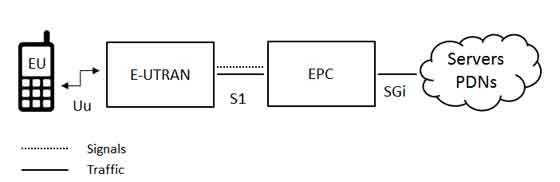
According to LTE Network Architecture and in TS 36.300 Figure 4.7.2-1, the high-level network architecture of LTE is comprised of following three main components:
- User Equipment (UE)
- Evolved UMTS Terrestrial Radio Access Network (E-UTRAN)
- Evolved Packet Core (EPC)
Protocol Architecture
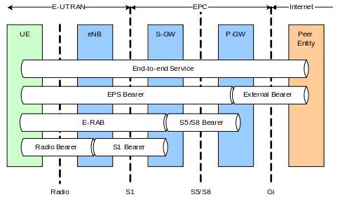
The following figure from TS 36.300-8c0 Figure 13.1-1 shows the EPS Bearer Service Architecture:
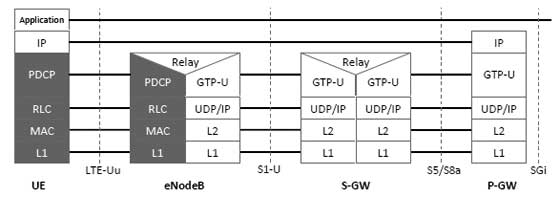
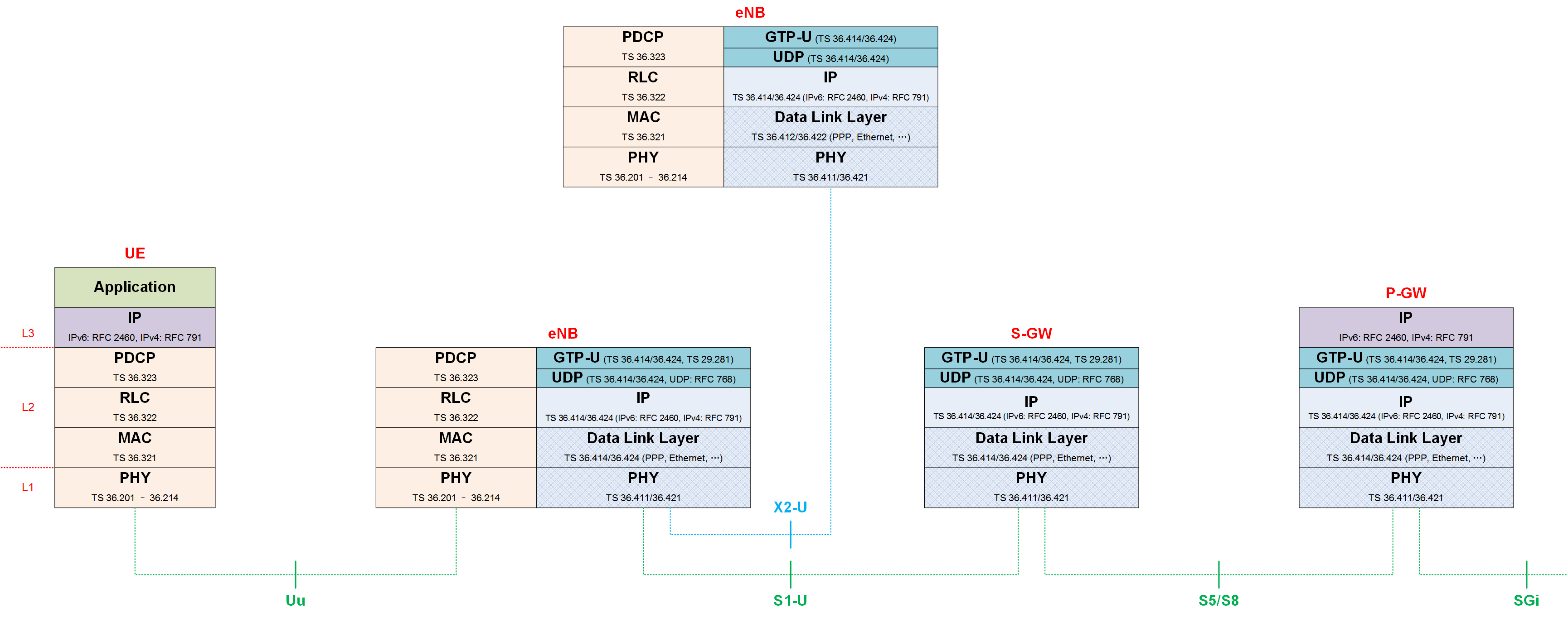
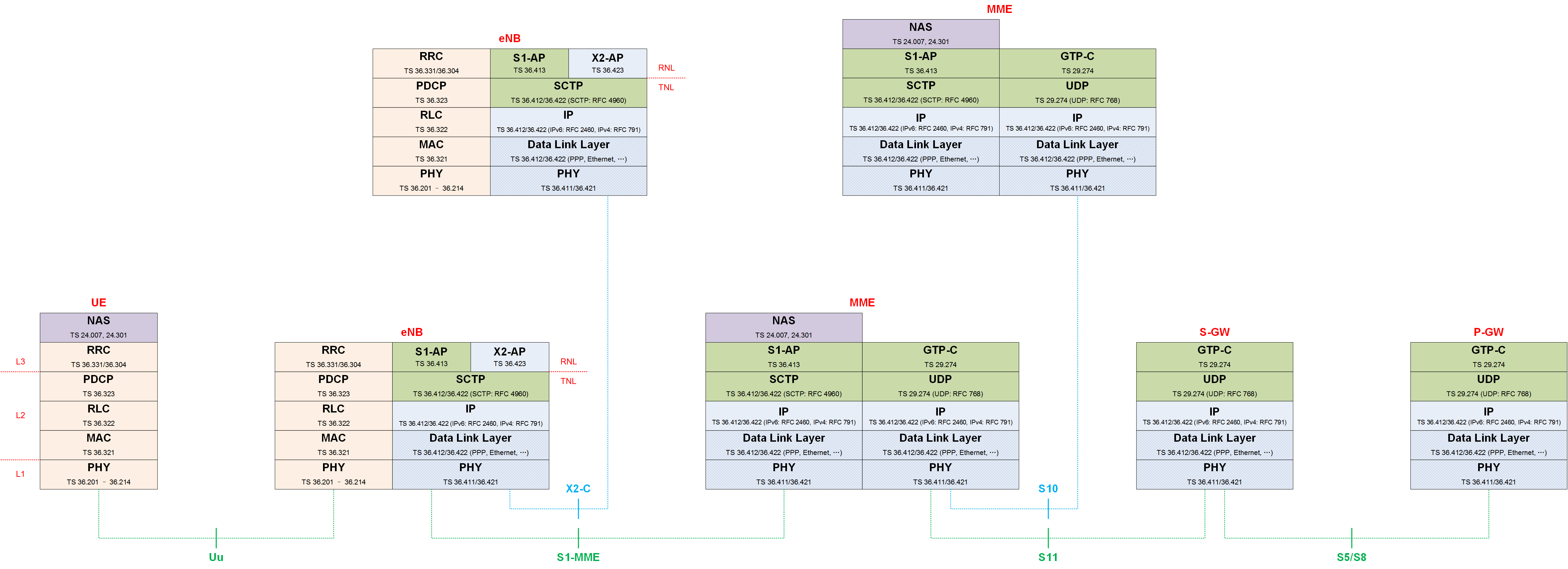
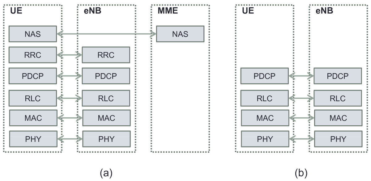
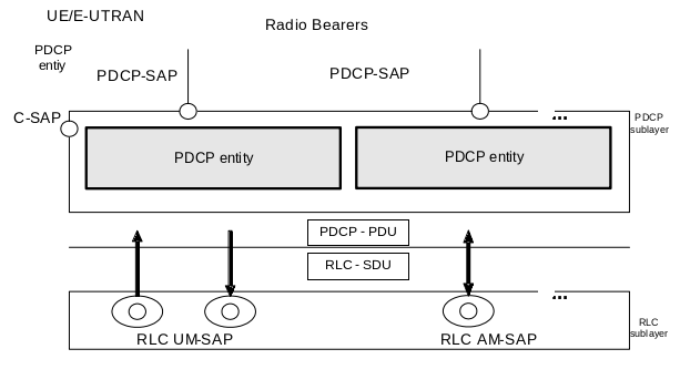
According to LTE Radio Protocol Architecture, TS 36.300-8c0 Figure 4.3.1-1, Figure 4.3.2-1, Figure 4.6.3.1-1 and Figure 4.6.3.2-1, the protocol architecture on User-plane is shown in the following figure:
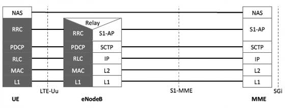
The protocol architecture on Control-plane is shown in the following figure:
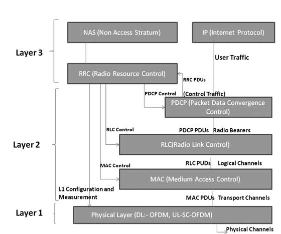
The Radio protocl architecture is shown in the following figure:
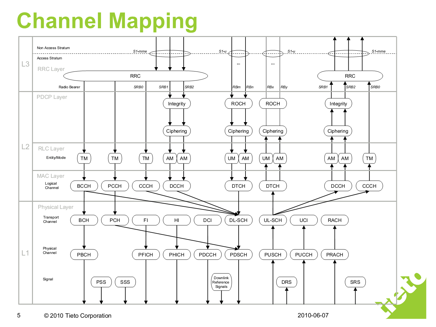
Channel Mapping
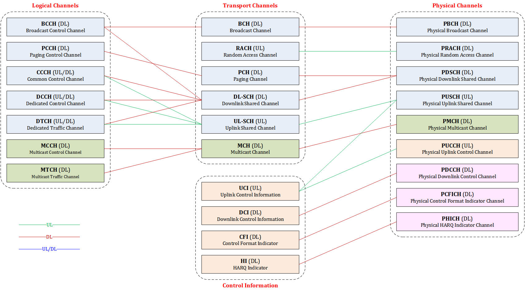
The logical channel is defined by what type of information is transferred. The transport channel is characterized by how the information is transferred over the radio interface.
According to TS 36.300, the following figure shows the channel mapping between logical channels, transport channels and physical channels:
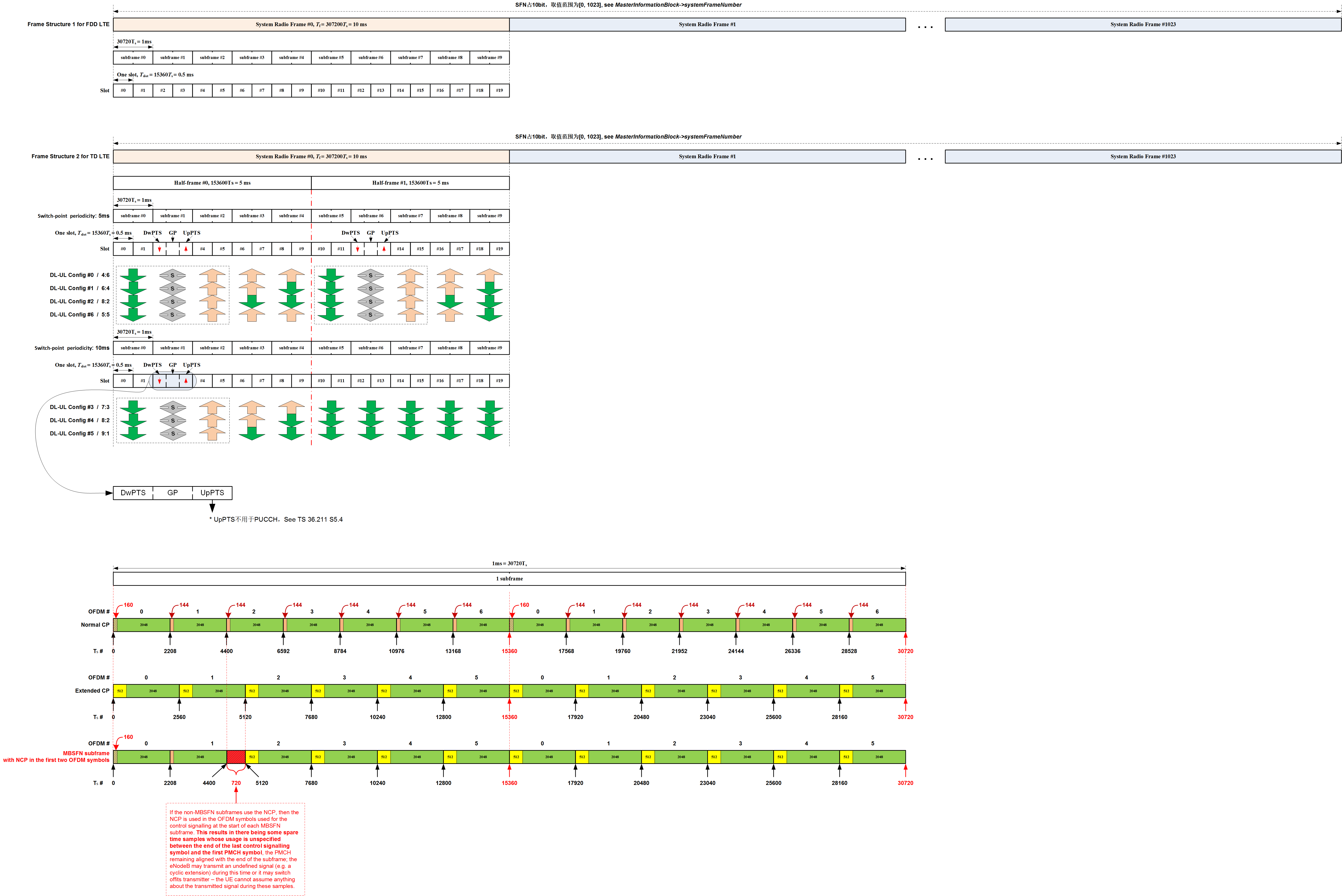
Frame Structure
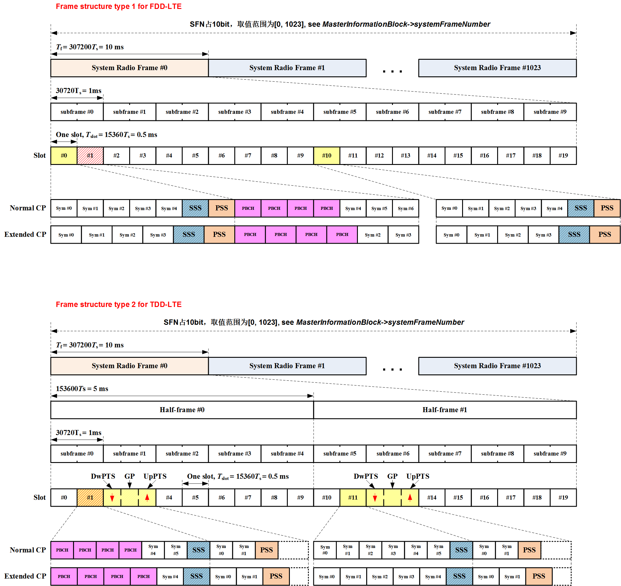
According to TS 36.211 Chapter 4, there are two types of frame structure in LTE:
- The frame structure type 1 is applicable to both full duplex and half duplex FDD-LTE.
- The frame structure type 2 is applicable to TDD-LTE.
User Equipment (UE)
The internal architecture of the user equipment (UE) for LTE is identical to the one used by UMTS and GSM which is actually a Mobile Equipment (ME). The mobile equipment comprised of the following important modules:
- Mobile Termination (MT): This handles all the communication functions.
- Terminal Equipment (TE): This terminates the data streams.
- Universal Integrated Circuit Card (UICC) : This is also known as the SIM card for LTE equipment. It runs an application known as the Universal Subscriber Identity Module (USIM). A USIM stores user-specific data very similar to 3G SIM card. This keeps information about the user’s phone number, home network identity and security keys etc.
UE related specifications include:
- TS 36.101-a70 User Equipment (UE) radio transmission and reception
- TS 36.304-a80 User Equipment (UE) procedures in idle mode
- TS 36.305-a50 Stage 2 functional specification of User Equipment (UE) positioning in E-UTRAN
Evolved UMTS Radio Access Network (E-UTRAN)
E-UTRAN Overview
The following specifications are related to E-UTRAN overview:
- TS 36.401-880 E-UTRAN Architecture description
- TS 36.300-8c0 E-UTRA and E-UTRAN Overall description - Stage 2
- TS 36.302-820 E-UTRA - Services provided by the physical layer
According to TS 23.401 S4.4.1, in addition to the E-UTRAN functions described in TS 36.300, E-UTRAN functions include:
- Header compression and user plane ciphering;
- MME selection when no routing to an MME can be determined from the information provided by the UE;
- UL bearer level rate enforcement based on UE-AMBR (Aggregate Maximum Bit Rate) and MBR (Maximum Bit Rate) via means of uplink scheduling (e.g. by limiting the amount of UL resources granted per UE over time);
- DL bearer level rate enforcement based on UE-AMBR (Aggregate Maximum Bit Rate);
- UL and DL bearer level admission control;
- Transport level packet marking in the uplink, e.g. setting the DiffServ Code Point, based on the QCI of the associated EPS bearer.
Radio Interface (Uu)
Refer to Protocol Architecture for the User-plane and Control-plane protocol layers of Uu interface.
Radio Resource Control (RRC)
- TS 36.331-8f0 E-UTRA - RRC Protocol specification
3GPP Message Decoder:
- Free Online 3GPP LTE ASN.1 Messages Decoder
- 3GPP Message Decoder
- 3GPP Decoder for LTE, UMTS and GSM
- 3GPP Message Decoder source code on GitHub
- 3GPP Decoder
RRC Services
The RRC protocol offers the following services to upper layers:
- Broadcast of common control information
- Notification of UEs in RRC_IDLE, e.g. about a terminating call, for ETWS
- Transfer of dedicated control information, i.e. information for one specific UE
The following are the main services that RRC expects from lower layers:
- PDCP: integrity protection and ciphering, refer to Packet Data Convergence Protocol (PDCP)
- RLC: reliable and in-sequence transfer of information, without introducing duplicates and with support for segmentation and concatenation, refer to Radio Link Control (RLC)
Packet Data Convergence Protocol (PDCP)
- TS 36.323-860 E-UTRA - Packet Data Convergence Protocol (PDCP) specification
- TS 36.314-830 E-UTRA - Layer 2 Measurements
- LTE PDCP on ShareTechnote or its local copy on GitHub
PDCP Services
PDCP provides its services to the RRC and user plane upper layers at the UE or to the relay at the evolved Node B (eNB). The following services are provided by PDCP to upper layers:
- transfer of user plane data;
- transfer of control plane data;
- header compression (U-plane only) using ROHC protocol;
- integrity protection (C-plane only);
- ciphering (U-plane and C-plane).
The maximum supported size of a PDCP SDU is 8188 octets.
PDCP Functions
According to TS 36.323-860 Chapter 4.4, the PDCP layer supports the following functions:
- header compression and decompression of IP data flows using the ROHC protocol;
- transfer of data (user plane or control plane);
- maintenance of PDCP SNs;
- in-sequence delivery of upper layer PDUs at re-establishment of lower layers;
- duplicate elimination of lower layer SDUs at re-establishment of lower layers for radio bearers mapped on RLC AM;
- ciphering and deciphering of user plane data and control plane data;
- integrity protection and integrity verification of control plane data;
- timer based discard;
- duplicate discarding.
PDCP uses the services provided by the RLC sublayer, also see RLC Functions:
- acknowledged data transfer service, including indication of successful delivery of PDCP PDUs;
- unacknowledged data transfer service;
- in-sequence delivery, except at re-establishment of lower layers;
- duplicate discarding, except at re-establishment of lower layers.
PDCP is used for SRBs and DRBs mapped on DCCH and DTCH type of logical channels. PDCP is not used for any other type of logical channels.
PDCP Procedures
The following figure from TS 36.323-860 Figure 4.2.1.1 shows the structure view of PDCP layer. PDCP is directly connected to RLC Layer, that’s RLC UM and RLC AM. And PDCP has no connection to RLC TM mode, meaning RLC TM mode data does not go through PDCP.
The following figure from TS 36.323-860 Figure 4.2.2.1 shows the functional view of PDCP layer:
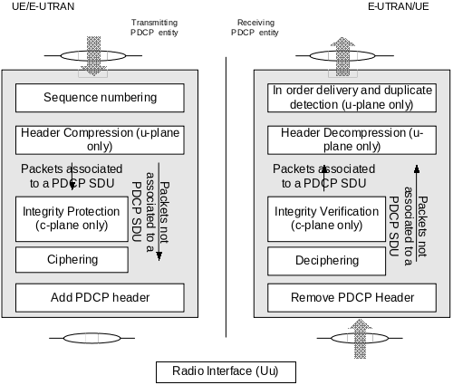
Let’s follow through the diagram from left side:
-
Data coming into PDCP first go through Sequence Numbering procedure. It means that PDCP add Sequence Number to each of incoming data block. Once it add Sequence Number, it has to manage the number. On reciever side, we can figure out many things like “Is the data getting delivered in order? Is there any duplicate data? How can I combine the multiple chunks of data block into an original big chunk data?”
-
Then it goes through Header Compression. But it says “this applies only to U-plane data”. It means that Signaling Message does not go through this Header Compression. Even though not shown in this diagram, we can disable Header Compression even for U-plane data (e.g, IP Packet data).
-
From here we see two paths, one through Integrity Protection / Ciphering and the other one directly goes to the last step. Integrity Protection applies only to C-Plane data (C-Plane data means RRC/NAS message, i.e DCCH data, not DTCH data). Again you can disable Integrity Protection step by applying EIA0 (EPS Integrity Algorithm) to this process. The Packets not associated to a PDCP SDU means the packets are generated in local PDCP layer, not from upper layers, such as, PDCP status report, Interspersed ROHC feedback packet, see TS 36.323 Table 6.3.8.1.
-
Then it goes to Ciphering process. Ciphering applies both C-Plane and U-Plane Data. Ciphering process can also be disabled by applying EEA0 (EPS Encryption Algorithms).
-
Eventually at the last step of transmission PDCP, a header is added and get out of PDCP layer.
PDCP PDU Formats
PDCP Data PDU format for SRBs
The following figure from TS 36.323 Figure 6.2.2.1. All the Control plane data (RRC/NAS message) from upper layer use this data structure:
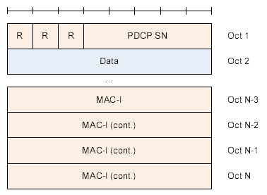
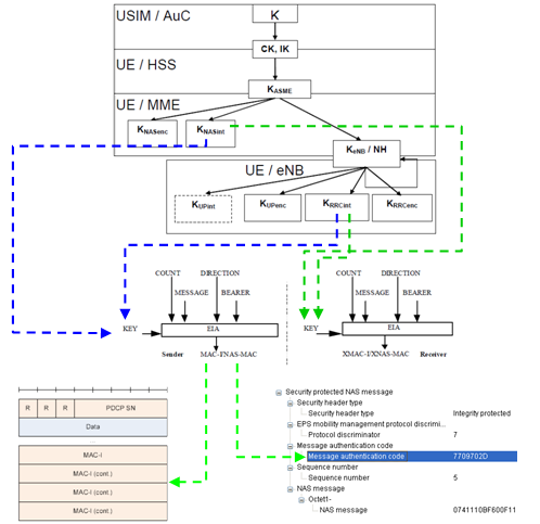
The MAC-I field carries a message authentication code calculated as specified in the following figure and TS 33.401:
PDCP Data PDU format for DRBs
The following two figures from TS 36.323 Figure 6.2.3.1 and Figure 6.2.4.1. All the User plane data from upper layer use this data structure with D/C == 1:
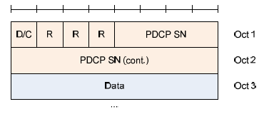
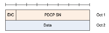
The length of field PDCP SN can be 7 or 12 bits, which is configured by IE PDCP-Config:
PDCP-Config ::=        SEQUENCE {
    ...
    rlc-UM             SEQUENCE {
        pdcp-SN-Size   ENUMERATED {len7bits, len12bits}
    }                  OPTIONAL, -- Cond Rlc-UM
    ...
}
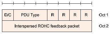
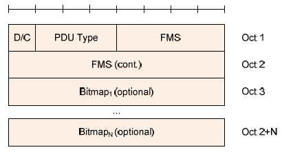
PDCP Control PDU formats for packets generated in local PDCP layer
The following two figures from TS 36.323 Figure 6.2.5.1 and Figure 6.2.6.1 are used for interspersed ROHC feedback packet and PDCP status report respectively with D/C == 0. Those packets are generated in local PDCP layer and sent to peer for control purpose:
ROHC Resources
- ROHC - Robust Header Compression: a free implementation of ROHC (Robust Header Compression) defined in RFC 3095
Radio Link Control (RLC)
- TS 36.322-880 E-UTRA - RLC protocol specification
- TS 36.314-830 E-UTRA - Layer 2 Measurements
RLC Services
The following services are provided by RLC to upper layer (i.e. RRC or PDCP):
- Transparent Mode (TM) data transfer;
- Unacknowledged Mode (UM) data transfer;
- Acknowledged Mode (AM) data transfer, including indication of successful delivery of upper layers PDUs.
RLC Functions
According to TS36.222-880 Chapter 4.4, the following functions are supported by the RLC sub layer:
- transfer of upper layer PDUs
- error correction through ARQ (only for AM data transfer)
- concatenation, segmentation and reassembly of RLC SDUs (only for UM and AM data transfer)
- re-segmentation of RLC data PDUs (only for AM data transfer)
- reordering of RLC data PDUs (only for UM and AM data transfer)
- duplicate detection (only for UM and AM data transfer)
- RLC SDU discard (only for UM and AM data transfer)
- RLC re-establishment
- Protocol error detection (only for AM data transfer)
RLC Procedures
The following figure from TS36.222-880 Figure 4.2.1-1 illustrates the overview model of the RLC sub layer:
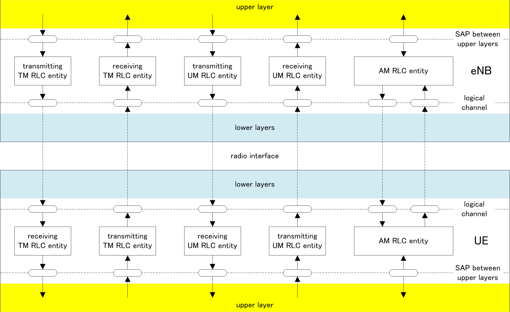
The following figure from TS 36.322-880 Figure 4.2.1.1.1-1 shows the model of two transparent mode (TM) peer entities. According to figures in PDCP Procedures, the RLC TM has no connection to PDCP layer, meaning RLC TM mode data does not go through PDCP.
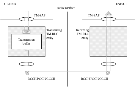
In RLC TM mode,
- It does not add or remove any header to the input data.
- It does not split the input data into multiple segment.
- It does not combine the multiple input data into a single big chunk.
The only operation operation being done in this mode is a buffering operation, but even this buffering operation is also very simple.
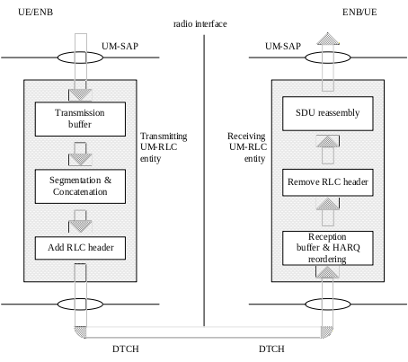
The following figure from TS 36.322-880 Figure 4.2.1.2.1-1 shows the model of two unacknowledged mode (UM) peer entities. According to figures in PDCP Procedures, the RLC UM is directly connected to PDCP layer.
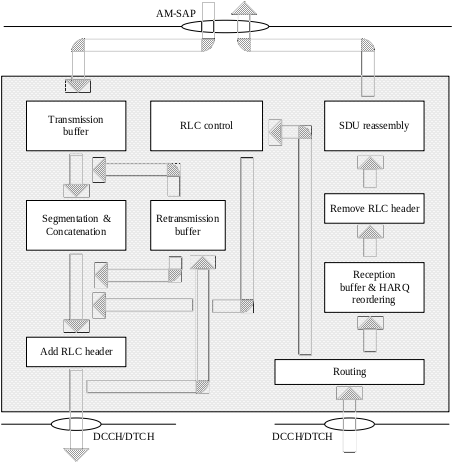
The following figure from TS 36.322-880 Figure 4.2.1.3.1-1 shows the model of two acknowledged mode (AM) peer entities. According to figures in PDCP Procedures, the RLC AM is directly connected to PDCP layer.
RLC PDU Formats
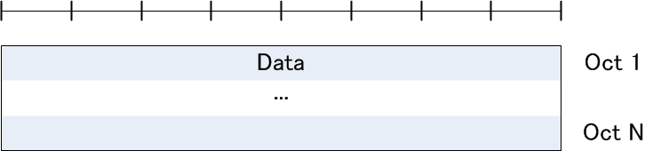
TMD PDU
TMD PDU is used to transfer upper layer PDUs by a TM RLC entity.
TMD PDU consists only of a Data field and does not consist of any RLC headers.
UMD PDU
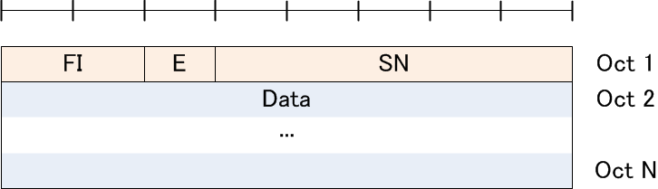
UMD PDU is used to transfer upper layer PDUs by an UM RLC entity.
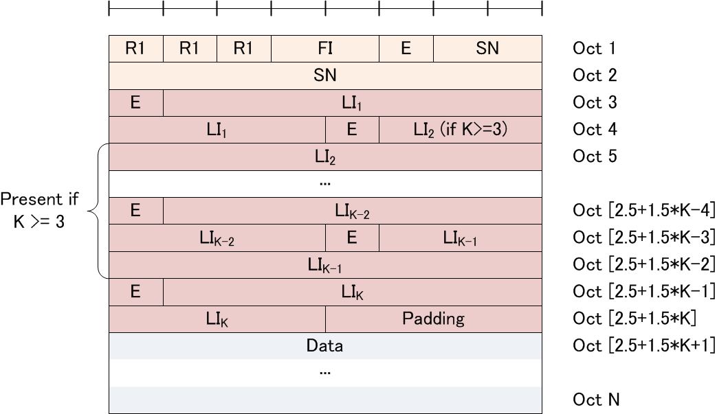
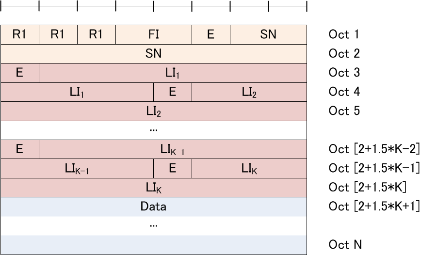
UMD PDU consists of a Data field and an UMD PDU header. An UM RLC entity is configured by RRC to use either a 5 bit SN or a 10 bit SN.
UMD PDU with 5 bit SN (No LI):
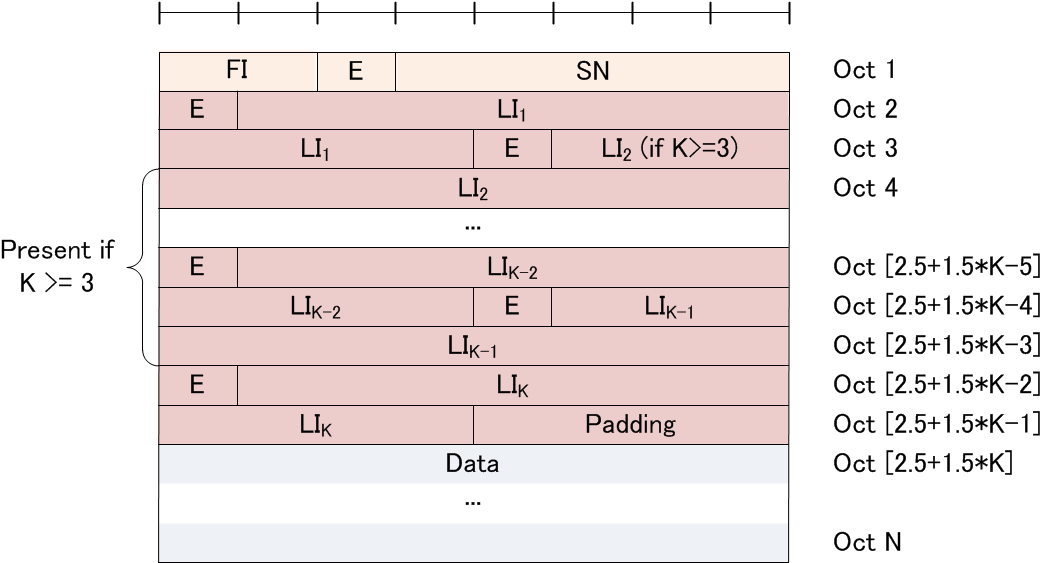
UMD PDU with 5 bit SN (Odd number of LIs, i.e. K = 1, 3, 5, …):
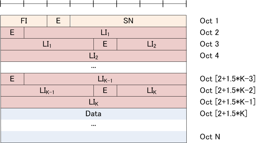
UMD PDU with 5 bit SN (Even number of LIs, i.e. K = 2, 4, 6, …):
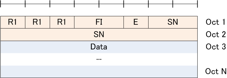
UMD PDU with 10 bit SN (No LI):
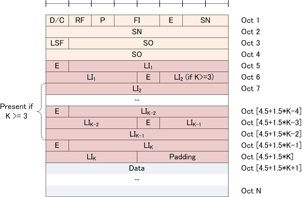
UMD PDU with 10 bit SN (Odd number of LIs, i.e. K = 1, 3, 5, …):
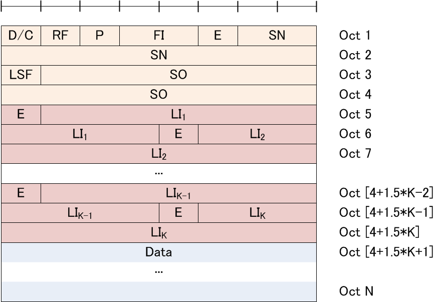
UMD PDU with 10 bit SN (Even number of LIs, i.e. K = 2, 4, 6, …):
AMD PDU
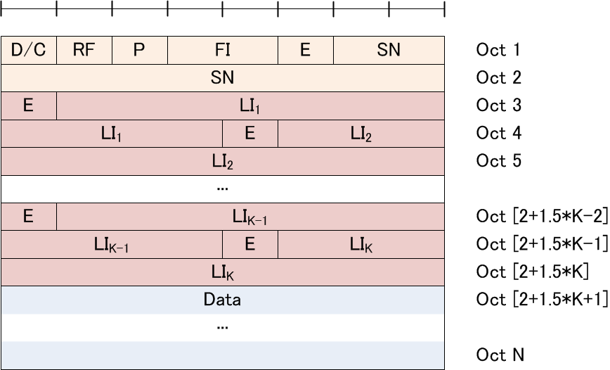
AMD PDU is used to transfer upper layer PDUs by an AM RLC entity. It is used when the AM RLC entity transmits (part of) the RLC SDU for the first time, or when the AM RLC entity retransmits an AMD PDU without having to perform re-segmentation.
AMD PDU consists of a Data field and an AMD PDU header, where D/C = 1, RF = 0.
AMD PDU (No LI):

AMD PDU (Odd number of LIs, i.e. K = 1, 3, 5, …):

AMD PDU (Even number of LIs, i.e. K = 2, 4, 6, …):
AMD PDU segment
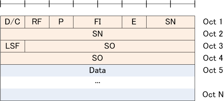
AMD PDU segment is used to transfer upper layer PDUs by an AM RLC entity. It is used when the AM RLC entity needs to retransmit a portion of an AMD PDU.
AMD PDU segment consists of a Data field and an AMD PDU segment header, where D/C = 1, RF = 1.
AMD PDU segment (No LI):
AMD PDU segment (Odd number of LIs, i.e. K = 1, 3, 5, …):
AMD PDU segment (Even number of LIs, i.e. K = 2, 4, 6, …):
STATUS PDU
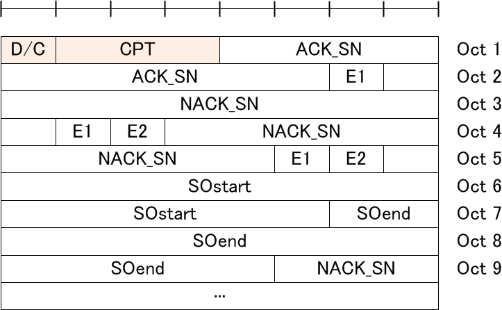
STATUS PDU is used by the receiving side of an AM RLC entity to inform the peer AM RLC entity about RLC data PDUs that are received successfully, and RLC data PDUs that are detected to be lost by the receiving side of an AM RLC entity.
STATUS PDU consists of a STATUS PDU payload and a RLC control PDU header, where D/C = 0.
Medium Access Control (MAC)
- TS 36.321-8a0 E-UTRA - MAC protocol specification
- TS 36.314-830 E-UTRA - Layer 2 Measurements
MAC Services
According to TS 36.321-8a0 Chapter 4.3.1, the following two kind of services are provided by MAC sublayer to upper layers:
- Data transfer
- Radio resource allocation
MAC Functions
According to TS 36.321-8a0 Chapter 4.4, the following functions are supported by MAC sublayer:
- mapping between logical channels and transport channels, refer to Channel Mapping;
- multiplexing of MAC SDUs from one or different logical channels onto transport blocks (TB) to be delivered to the physical layer on transport channels;
- demultiplexing of MAC SDUs from one or different logical channels from transport blocks (TB) delivered from the physical layer on transport channels;
- scheduling information reporting;
- error correction through HARQ;
- priority handling between UEs by means of dynamic scheduling;
- priority handling between logical channels of one UE;
- logical channel prioritisation;
- transport format selection.
MAC Procedures
Refer to TS 36.321-8a0 Chapter 5.
MAC PDU Formats
MAC PDU (DL-SCH and UL-SCH except transparent MAC and Random Access Response)
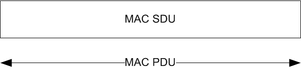
A MAC PDU consists of a MAC header, zero or more MAC Service Data Units (MAC SDU), zero, or more MAC control elements, and optionally padding. MAC control elements are always placed before any MAC SDU. Both the MAC header and the MAC SDUs are of variable sizes. A maximum of one MAC PDU can be transmitted per TB per UE.
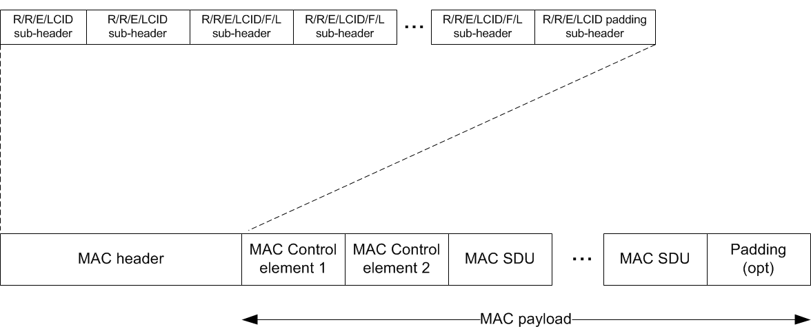
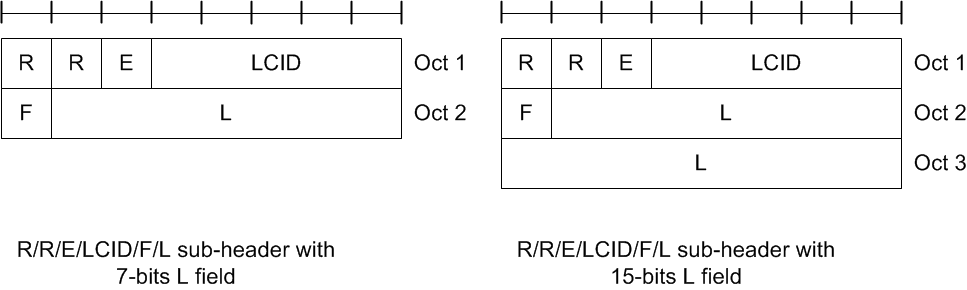
A MAC PDU header consists of one or more MAC PDU subheaders; each subheader corresponds to either a MAC SDU, a MAC control element or padding. MAC PDU subheaders have the same order as the corresponding MAC SDUs, MAC control elements and padding.
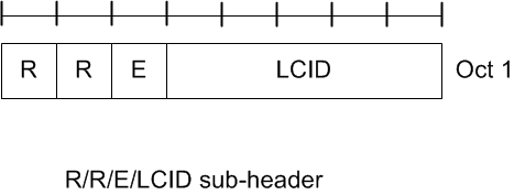
A MAC PDU subheader consists of the six header fields R/R/E/LCID/F/L but for the last subheader in the MAC PDU and for fixed sized MAC control elements. The last subheader in the MAC PDU and subheaders for fixed sized MAC control elements consist solely of the four header fields R/R/E/LCID.
The MAC Control Elements include the followings, refer to TS 36.321-8a0 Chapter 6.1.3 for details:
- Buffer Status Report MAC Control Elements
- C-RNTI MAC Control Element
- DRX Command MAC Control Element
- UE Contention Resolution Identity MAC Control Element
- Timing Advance Command MAC Control Element
- Power Headroom MAC Control Element
MAC PDU (transparent MAC)
A MAC PDU consists solely of a MAC Service Data Unit (MAC SDU) whose size is aligned to a TB.
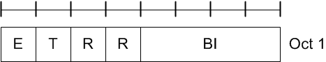
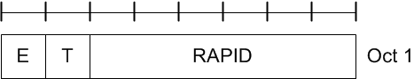
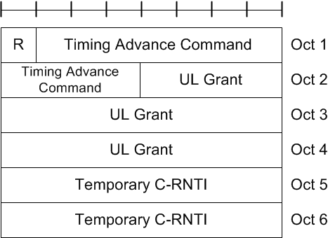
MAC PDU (Random Access Response)
A MAC PDU consists of a MAC header and zero or more MAC Random Access Responses (MAC RAR) and optionally padding.
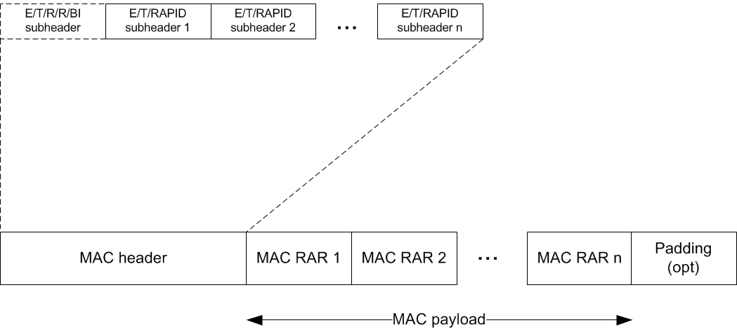
The MAC header is of variable size.
A MAC PDU header consists of one or more MAC PDU subheaders; each subheader corresponding to a MAC RAR except for the Backoff Indicator subheader. If included, the Backoff Indicator subheader is only included once and is the first subheader included within the MAC PDU header.
Physical Layer (L1)
- TS 36.302-821 E-UTRA - Services provided by the physical layer
- TS 36.201-830 E-UTRA - LTE Physical Layer General Description
- TS 36.211-890 E-UTRA - Physical Channels and Modulation
- TS 36.212-880 E-UTRA - Multiplexing and channel coding
- TS 36.213-880 E-UTRA - Physical layer procedures
- TS 36.214-870 E-UTRA - Physical layer Measurements
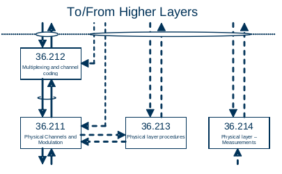
The following figure from TS 36.201-830 Figure 2 shows the relation between the physical layer specifications:
L1 Services
According to TS 36.201-830 Chapter 4.1.2, the physical layer offers data transport services to higher layers. The access to these services is through the use of a transport channel via the MAC sub-layer.
Also refer to TS 36.302-821 E-UTRA - Services provided by the physical layer.
L1 Functions
According to TS 36.201-830 Chapter 4.1.2, the physical layer is expected to perform the following functions in order to provide the data transport service:
- Error detection on the transport channel and indication to higher layers
- FEC encoding/decoding of the transport channel
- Hybrid ARQ soft-combining
- Rate matching of the coded transport channel to physical channels
- Mapping of the coded transport channel onto physical channels
- Power weighting of physical channels
- Modulation and demodulation of physical channels
- Frequency and time synchronisation
- Radio characteristics measurements and indication to higher layers
- Multiple Input Multiple Output (MIMO) antenna processing
- Transmit Diversity (TX diversity)
- Beamforming
- RF processing (Note: RF processing aspects are specified in the TS 36.100 series)
L1 Procedures
According to TS 36.201-830 Chapter 4.2.4, there are several Physical layer procedures involved with LTE operation. Such procedures covered by the physical layer are:
- Cell search
- Power control
- Uplink synchronisation and Uplink timing control
- Random access related procedures
- HARQ related procedures
S1 Interface
The S1 interfaces related specifications are:
- TS 36.410-830 E-UTRAN - S1 general aspects and principles
- TS 36.411-810 E-UTRAN - S1 layer 1
- TS 36.412-860 E-UTRAN - S1 signaling transport
- TS 36.413-8a0 E-UTRAN - S1 Application Protocol (S1AP)
- TS 36.414-840 E-UTRAN - S1 data transport
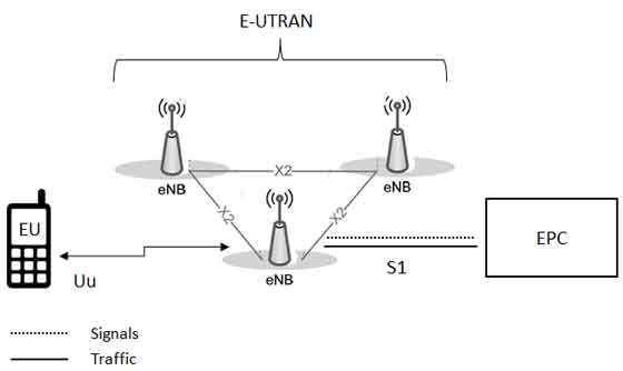
The S1 interface connects the Evolved NodeB (eNB) component of the E-UTRAN to the Core Network of the SAE system, refer to Network Architecture, Protocol Architecture and the following figure:
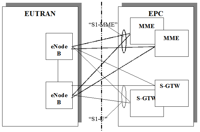
From the S1 perspective, the E-UTRAN access point is an eNB, and the EPC access point is either the control plane MME logical node or the user plane S-GW logical node. Two types of S1 interfaces are thus defined at the boundary depending on the EPC access point: S1-MME towards an MME and S1-U towards an S-GW.
The S1 is a logical interface. The S1 is a point-to-point interface between an eNB within the E-UTRAN and an MME in the EPC. A point-to-point logical interface should be feasible even in the absence of a physical direct connection between the eNB and MME.
X2 Interface
The X2 interfaces related specifications are:
- TS 36.420-810 E-UTRAN - X2 general aspects and principles
- TS 36.421-800 E-UTRAN - X2 layer 1
- TS 36.422-860 E-UTRAN - X2 signaling transport
- TS 36.423-890 E-UTRAN - X2 application protocol (X2AP)
- TS 36.424-850 E-UTRAN - X2 data transport
The S1 interface connects two E-UTRAN NodeB (eNB) components within the E-UTRAN architecture, refer to Network Architecture and Protocol Architecture.
The X2 is a point-to-point interface between two eNBs within the E-UTRAN. A point-to-point logical interface should be feasible even in the absence of a physical direct connection between the two eNBs.
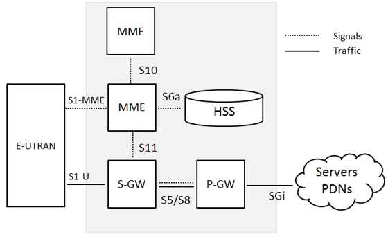
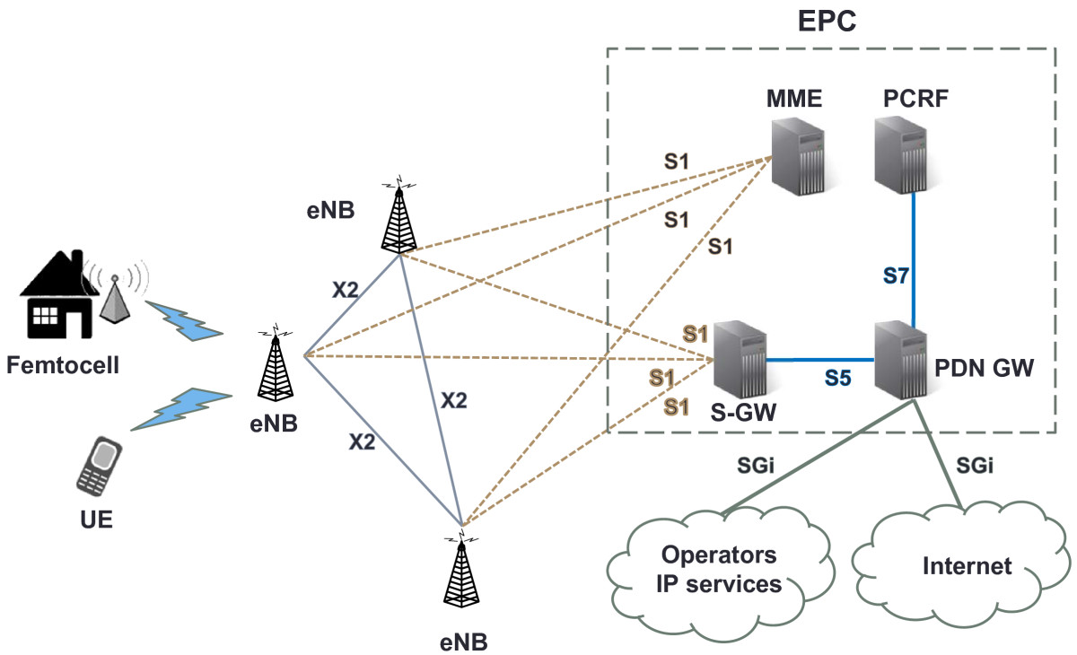
Evolved Packet Core (EPC)
EPC Entities
Mobility Management Entity (MME)
According to TS 23.401 S4.4.2, MME functions include:
- NAS signalling;
- NAS signalling security;
- Inter CN node signalling for mobility between 3GPP access networks (terminating S3);
- UE Reachability in ECM-IDLE state (including control and execution of paging retransmission);
- Tracking Area list management;
- PDN GW and Serving GW selection;
- MME selection for handovers with MME change;
- SGSN selection for handovers to 2G or 3G 3GPP access networks;
- Roaming (S6a towards home HSS);
- Authentication;
- Authorization;
- Bearer management functions including dedicated bearer establishment;
- Lawful Interception of signalling traffic;
- Warning message transfer function (including selection of appropriate eNodeB);
- UE Reachability procedures.
NOTE: The S-GW and the MME may be implemented in one physical node or separated physical nodes.
Serving GW (S-GW)
According to TS 23.401 S4.4.3.2, the Serving GW is the gateway which terminates the interface towards E-UTRAN. For each UE associated with the EPS, at a given point of time, there is a single Serving GW. The functions of the Serving GW, for both the GTP-based and the PMIP-based S5/S8, include:
- the local Mobility Anchor point for inter-eNodeB handover;
- sending of one or more “end marker” to the source eNodeB, source SGSN or source RNC immediately after switching the path during inter-eNodeB and inter-RAT handover, especially to assist the reordering function in eNodeB.
- Mobility anchoring for inter-3GPP mobility (terminating S4 and relaying the traffic between 2G/3G system and PDN GW);
- ECM-IDLE mode downlink packet buffering and initiation of network triggered service request procedure;
- Lawful Interception;
- Packet routing and forwarding;
- Transport level packet marking in the uplink and the downlink, e.g. setting the DiffServ Code Point, based on the QCI of the associated EPS bearer;
- Accounting for inter-operator charging. For GTP-based S5/S8, the Serving GW generates accounting data per UE and bearer;
- Interfacing OFCS according to charging principles and through reference points specified in TS 32.240.
Additional Serving GW functions for the PMIP-based S5/S8 are captured in TS 23.402. Connectivity to a GGSN is not supported.
NOTE: The P-GW and S-GW may be implemented in one physical node or separated physical nodes.
PDN GW (P-GW)
According to TS 23.401 S4.4.3.3, the PDN GW is the gateway which terminates the SGi interface towards the PDN. If a UE is accessing multiple PDNs, there may be more than one PDN GW for that UE, however a mix of S5/S8 connectivity and Gn/Gp connectivity is not supported for that UE simultaneously. PDN GW functions include for both the GTP-based and the PMIP-based S5/S8:
- Per-user based packet filtering (by e.g. deep packet inspection);
- Lawful Interception;
- UE IP address allocation;
- Transport level packet marking in the uplink and downlink, e.g. setting the DiffServ Code Point, based on the QCI of the associated EPS bearer;
- Accounting for inter-operator charging;
- UL and DL service level charging as defined in TS 23.203 (e.g. based on SDFs defined by the PCRF, or based on deep packet inspection defined by local policy);
- Interfacing OFCS through according to charging principles and through reference points specified in TS 32.240.
- UL and DL service level gating control as defined in TS 23.203;
- UL and DL service level rate enforcement as defined in TS 23.203 (e.g. by rate policing/shaping per SDF);
- UL and DL rate enforcement based on APN-AMBR (e.g. by rate policing/shaping per aggregate of traffic of all SDFs of the same APN that are associated with Non-GBR QCIs);
- DL rate enforcement based on the accumulated MBRs of the aggregate of SDFs with the same GBR QCI (e.g. by rate policing/shaping);
- DHCPv4 (server and client) and DHCPv6 (client and server) functions;
- The network does not support PPP bearer type in this version of the specification. Pre-Release 8 PPP functionality of a GGSN may be implemented in the PDN GW;
- packet screening.
Additionally the PDN GW includes the following functions for the GTP-based S5/S8:
- UL and DL bearer binding as defined in TS 23.203;
- UL bearer binding verification as defined in TS 23.203;
- Functionality as defined in RFC 4861;
- Accounting per UE and bearer.
The P-GW provides PDN connectivity to both GERAN/UTRAN only UEs and E-UTRAN capable UEs using any of E-UTRAN, GERAN or UTRAN. The P-GW provides PDN connectivity to E-UTRAN capable UEs using E-UTRAN only over the S5/S8 interface.
NOTE: The P-GW and S-GW may be implemented in one physical node or separated physical nodes.
Interfaces
S10 Interface
S10 is a control interface between the MMEs which will be very similar to the S3 interface between the SGSN and MME. The interface is based on Gn/GTP-Control (GTP-C) (interface between SGSN-SGSN) with additional functionality. It is used for user information transfer as well as MME relocation support. Refer to TS 29.274 GTPv2-C.
S10 is a many-to-many interface.
S11 Interface
S11 is the interface between the MME and S-GW. The interface is based on Gn/GTP-Control (GTP-C) (interface between SGSN-GGSN) with some additional functions for paging coordination, mobility compared to the legacy Gn/GTP-C (SGSN-GGSN) interface. It is used to support mobility and bearer management. Refer to TS 29.274 GTPv2-C.
S11 is a many-to-many interface.
S5/S8 Interface
S5/S8 is the reference point between S-GW and PDN-GW. It provides user plane tunneling and tunnel management. S8 is inter-PLMN variant of S5 interface.
S6a Interface
TS 29.272: Mobility Management Entity (MME) and Serving GPRS Support Node (SGSN) related interfaces based on Diameter protocol
SGi Interface
SGi is the reference point between the PDN Gateway (P-GW) and the packet data network. Packet data network may be an operator external public or private packet data network or an intra operator packet data network, e.g. for provision of IMS services. This reference point corresponds to Gi for 3GPP accesses. Refer to TS 29.061.
Technical Components of LTE
Orthogonal Frequency Division Multiplexing (OFDM)
Orthogonal Frequency Division Multiplexing (OFDM) is a particular form of multi-carrier transmission and is suited for frequency selective channels and high data rates. This technique transforms a frequency-selective wide-band channel into a group of non-selective narrowband channels, which makes it robust against large delay spreads by preserving orthogonality in the frequency domain. Moreover, the ingenious introduction of cyclic redundancy at the transmitter reduces the complexity to only FFT processing and one tap scalar equalization at the receiver. Refer to Short Introduction to OFDM for details.
Diversity
There are basically two types of Diversity called Reciever Diversity and Transmitter Diversity.
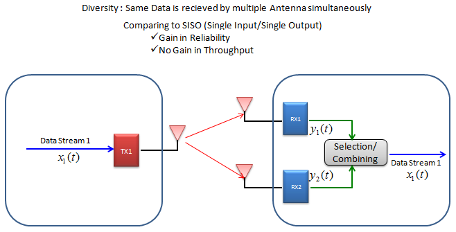
Reciever Diversity
In Reciever Diversity configuration, single copy of one bit stream is being transmitted and reaches to multiple reciever antenna via a little different path, it means the reciever can have multiple versions of same data. Out of the multiple version, the reciever can select the best one or combine them all together in such a way to improve data quality. By doing this, communication reliability (less error) can be increased, but no advantage in terms data throughput.
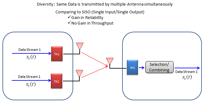
Transmitter Diversity
In Transmitter Diversity configuration, multiple copies of one (single) bit stream is being transmitted via multiple Tx antenna and reaches to single reciever antenna via a little different path, it means the reciever can have multiple versions of same data. Out of the multiple version, the reciever can select the best one or combine them all together in such a way to improve data quality. By doing this, communication reliability (less error) can be increased, but no advantage in terms data throughput.
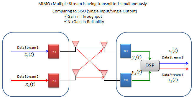
Multiple Input Multiple Output (MIMO)
Multiple Input Multiple Output (MIMO) is a technique to increase the data throughput by using multiple transmitter antenna and multiple reciever antenna. However, there is almost no advantage in terms of reliability of data transfer (e.g, less error) comparing to Single Input Single Output (SISO) case.
Refer to LTE MIMO on ShareTechnote or its local copy on GitHub, and Assessing a MIMO Channel.
BeamForming
Refer to documtents:
- LTE BeamForming on ShareTechnote or its local copy on GitHub
- Meeting_the_Needs_of_Midmarket_Firms
- Wireless_LAN_Design_Guide_for_High_Density_Client_Environments_in_Higher_Education
This is mainly for WLAN, but can be a good introduction:
-
Switched Array Antenna: This is the technique that change the beam pattern (radiation form) by switching on/off antenna selectively from the array of a antenna system.
-
DSP Based Phase Manipulation: This is the technique that change the beam pattern (radiation form) by changing the phase of the signal going through each antenna. Using DSP, you can change the signal phase for each antenna port differently to form a specific beam pattern that is best fit for one or multiple specific UEs.
-
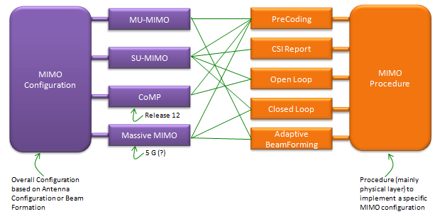
Beamforming by Precoding: This is the technique that change the beam pattern (radiation form) by applying a specific precoding matrix. This is the technique used in LTE. In LTE, following transmission mode is implemeting ‘BeamForming’ implictely or explicitely.
- TM 6 - Closed loop spatial multiplexing using a single transmission layer
- TM 7 - Beamforming (Antenna port 5)
- TM 8 - Dual Layer Beamforming (Antenna ports 7 and 8)
Inter-Cell Interference Coordination (ICIC)
Background:
-
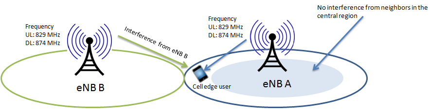
LTE is designed for frequency reuse (To maximize spectrum efficiency), which means that all the neighbor cells are using same frequency channels and therefore there is no cell-planning to deal with the interference issues.
-
There is a high probability that a resource block scheduled to cell edge user, is also being transmitted by neighbor cell, resulting in high interference, eventually low throughput or call drops, see below figure.
-
Traffic channel can sustain upto 10% of BLER in low SINR but control channels cannot. Neighbor interference can result in radio link failures at cell edge.
-
Heterogeneous networks require some sort of interference mitigation, since pico-cells/femto cells and macro-cells are overlapping in many scenarios
Inter-Cell Interference Coordination (ICIC) for LTE:
-
Inter-cell interference coordination is introduced in 3GPP release 8.
-
ICIC is introduced to deal with interference issues at cell-edge.
-
ICIC mitigates interference on traffic channels only.
-
ICIC uses power and frequency domain to mitigate cell-edge interference from neighbor cells.
-
One scheme of ICIC is where neighbor eNBs use different sets of resource blocks through out the cell at given time i.e. no two neighbor eNBs will use same resource assignments for their UEs. This greatly improves cell-edge SINR. The disadvantage is decrease in throughput throughout the cell, since full resources blocks are not being utilized.
-
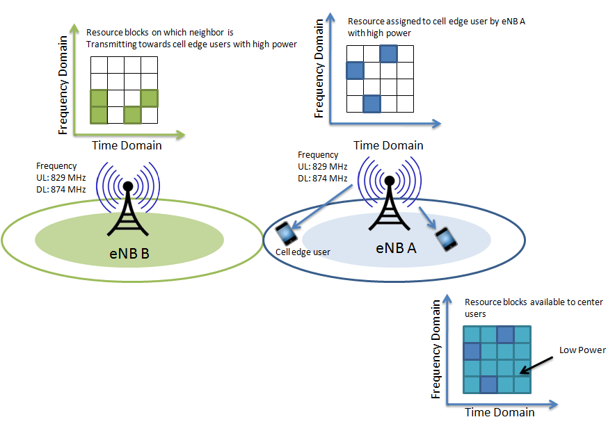
In the second scheme, all eNBs utilize complete range of resource blocks for centrally located users but for cell-edge users, no two neighbor eNBs uses the same set of resource blocks at give time.
-
In the third scheme (probably the preferred scheme), all the neighbor eNBs use different power schemes across the spectrum while resource block assignment can be according to second scheme explained above. For example, eNB can use power boost for cell edge users with specific set of resources (not used by neighbors), while keeping low signal power for center users with availability of all resource blocks, see below figure.
-
X2 interface is used to share the information between the eNBs.
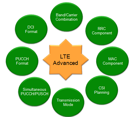
Technical Components of LTE-Advanced
The followings are the technical components to implement LTE-Advanced:
Also refer to article Overview of Enabling Technologies for 3GPP LTE-Advanced on SpringerOpen website or its local copy on GitHub.
Carrier Aggregation (CA)
3GPP Specifications
Refer to the 3GPP_Carrier Aggregation for LTE_20141015.zip on 3GPP FTP site.
Refer to the artical Carrier Aggregation explained on 3GPP website or its local copy on GitHub for explainations of carrier aggregation.
Refer to the artical LTE CA: Carrier Aggregation Tutorial on Radio-Electronic.com or its local copy on GitHub for the tutorial of carrier aggregation.
And read the following specifications:
- TR 36.808 Evolved Universal Terrestrial Radio Access (E-UTRA); Carrier Aggregation; Base Station (BS) radio transmission and reception
- TR 36.814 Evolved Universal Terrestrial Radio Access (E-UTRA); Further advancements for E-UTRA physical layer aspects
- TR 36.815 Further Advancements for E-UTRA; LTE-Advanced feasibility studies in RAN WG4
- TR 36.823 Evolved Universal Terrestrial Radio Access (E-UTRA); Carrier Aggregation Enhancements; UE and BS radio transmission and reception
- TR 36.912 Feasibility study for Further Advancements for E-UTRA (LTE-Advanced)
- TR 36.913 Requirements for further advancements for Evolved Universal Terrestrial Radio Access (E-UTRA) (LTE-Advanced)
- TS 36.101 Evolved Universal Terrestrial Radio Access (E-UTRA); User Equipment (UE) radio transmission and reception
- TS 36.101-e30 Section 5.6A: Channel bandwidth for CA
- TS 36.101-e30 Table 5.6A-1: CA bandwidth classes and corresponding nominal guard bands
- TS 36.101-e30 Section 5.7.1A: Channel spacing for CA
- TS 36.101-e30 Section 5.7.2A: Channel raster for CA
- TS 36.101-e30 Section 5.7.4A: TX–RX frequency separation for CA
- TS 36.211 Evolved Universal Terrestrial Radio Access (E-UTRA); Physical channels and modulation
- TS 36.212 Evolved Universal Terrestrial Radio Access (E-UTRA); Multiplexing and channel coding
- TS 36.213 Evolved Universal Terrestrial Radio Access (E-UTRA); Physical layer procedures
- TS 36.300 Evolved Universal Terrestrial Radio Access (E-UTRA) and Evolved Universal Terrestrial Radio Access Network (E-UTRAN); Overall description; Stage 2
Initial Motivation for Carrier Aggregation
Does this mean that they already feel the current 20 Mhz LTE bandwidth is not enough? As far as I know, it is not because of this. Even though the current LTE supports 20 Mhz BW in maximum, there are only a few network operators who is certified for such a wide bandwidth. The most common bandwidth that network operators has for LTE is 10 Mhz, which means they are not fully utilizing the LTE capability in terms of bandwidth. This is not because of technical restriction, it is purely because of licensing issues for the allocated bandwidth.
Even though there is not many Network Operators who has 20 Mhz BW, there are some network operators who has license multiple band (e.g, two separated 10 Mhz BW and two or more 5 Mhz BW). These network operators wants to combine those multiple bands to achieve wide BW (in most case 20 Mhz BW) LTE. It is the initial motivation for LTE Advanced for now.
What is Carrier Aggregation?
Carrier Aggregation is a special form of LTE technology that enables UE and Network to use more than one carrier frequencies. Actually this is not a new concept in LTE. You might have used/heard Dual Carrier in WCDMA HSDPA (HSDPA DC) or similar mode in WiFi (I forgot the terminology in WiFi).
Types of Carrier Aggregation
There are three types of carrier aggregation:
- intra-band contiguous carrier aggregation
- intra-band non-contiguous carrier aggregation
- inter-band non-contiguous carrier aggregation
How can I know which band combination of bands a UE support in terms of Carrier Aggregation?
It is also supposed to be reported to network by the UE via UE Capability Information message. Followings are some of the possible IEs a UE may use depending on its release status, refer to TS 36.331:
RF-Parameters-v1020 ::= SEQUENCE {
    supportedBandCombination-r10    SupportedBandCombination-r10
}

RF-Parameters-v1090 ::= SEQUENCE {
    supportedBandCombination-v1090  SupportedBandCombination-v1090  OPTIONAL
}

RF-Parameters-v1130 ::= SEQUENCE {
    supportedBandCombination-v1130  SupportedBandCombination-v1130  OPTIONAL
}
Refer to the following tables for all the possible (allowed) band combination of inter-band and intra-band CA case:
- TS 36.101-e30 Table 5.6A-1: CA bandwidth classes and corresponding nominal guard bands
- TS 36.101-e30 Table 5.6A.1-1: E-UTRA CA configurations and bandwidth combination sets defined for intra-band contiguous CA
- TS 36.101-e30 Table 5.6A.1-2: E-UTRA CA configurations and bandwidth combination sets defined for inter-band CA (two bands)
- TS 36.101-e30 Table 5.6A.1-2a: E-UTRA CA configurations and bandwidth combination sets defined for inter-band CA (three bands)
- TS 36.101-e30 Table 5.6A.1-2b: E-UTRA CA configurations and bandwidth combination sets defined for inter-band CA (four bands)
- TS 36.101-e30 Table 5.6A.1-2c: E-UTRA CA configurations and bandwidth combination sets defined for inter-band CA (five bands)
- TS 36.101-e30 Table 5.6A.1-3: E-UTRA CA configurations and bandwidth combination sets defined for non-contiguous intra-band CA (with two sub-blocks)
Clustered SC-FDMA (Enhanced UL Transmission)
The original SC-FDMA was designed to work in a contiguous band. In order to support carrier aggregation in the UL as well as the DL, the LTE-Advanced adopts a modified version of SC-FDMA, which is referred to as clustered SC-FDMA.
The use of clustered SC-FDMA allows non-contiguous bands for UL transmission, and thus enables frequency selective scheduling within a CC. However, the number of clusters is limited to two in release 10, since the clustering usually degrades the PAPR performance due to destruction of single carrier characteristic in the time domain. Another aspect of the carrier aggregation is that different sets of CC’s can be assigned to the DL and UL. Moreover, even within the same cell, different UE’s will work with different numbers of CC’s, depending on their capabilities, channel condition, and so on.
Enhanced MIMO
Multiple-input multiple-output (MIMO) refers to a communication system that is equipped with multiple antennas at both transmit and receive sides. The use of MIMO was a key that led to success of IEEE 802.11n, HSPA, and LTE, and now MIMO continues its journey with the LTE-Advanced. According to the LTE-Advanced requirements, the maximum spectral efficiency must be as high as 30 bps/Hz in the DL, which requires the use of 8 × 8 MIMO spatial multiplexing. The DL MIMO was already supported in the LTE in the form of transmit diversity and closed-loop spatial multiplexing up to four layers. The LTE-Advanced adopts a closed-loop precoding to realize 8 × 8 MIMO spatial multiplexing.
The MIMO transmission is supported in the UL as well. Unlike the LTE that does not support single user MIMO in the UL, the LTE-Advanced supports MIMO with two or four layers. Note that the maximum spectral efficiency of 15 bps/Hz can be attained only using spatial multiplexing with four layers.
Relay Node
One of the key modification of LTE advanced is wireless Relay Node to improve data communication especially on cell boundary and increase cell coverage.
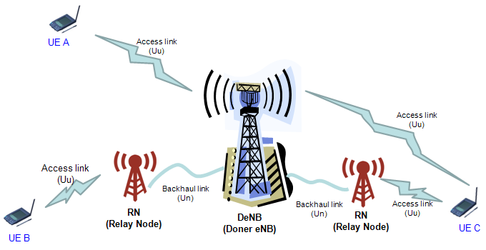
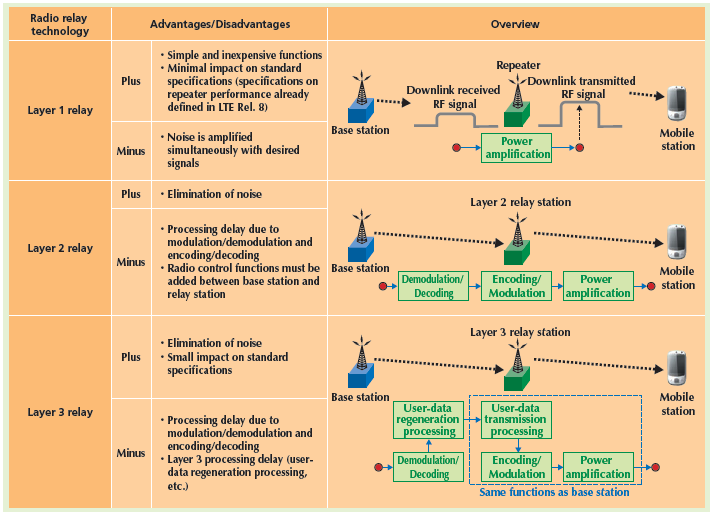
The following table from NTT DoCoMo technical report:
enhanced Inter-Cell Interference Coordination (eICIC)
enhanced Inter-Cell Interference Coordination (eICIC) for LTE-Advanced:
-
eICIC introduced in 3GPP release 10.
-
eICIC introduced to deal interference issues in Heterogeneous Networks (HetNet).
-
eICIC mitigates interference on traffic and control channels.
-
eICIC uses power, frequency and also time domain to mitigate intra-frequency interference in heterogeneous networks.
-
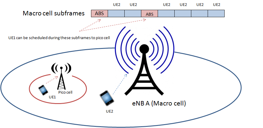
eICIC introduces concept of Almost Blank Subframe (ABS). ABS subframes do not send any traffic channels and are mostly control channel frames with very low power. If macro cell configure ABS subframes then UEs connected to pico/femto cells can send their data during such ABS frames and avoid interference from macro cell, see below figure.
-
ABS configuration is shared via OAM or X2 interface.
Refer to ICIC (Inter-Cell Interference Coordination) for descriptions of ICIC and its solution:
With an explosive growth in wireless traffic, a variety of small-size low-power base stations are being deployed within the usual macro eNB to serve hot zone, office, and home areas. This type of overlay architecture is referred to as heterogeneous network (HetNet). The below table shows several types of nodes that may exist in a HetNet. Different types of nodes are optimized for better coverage and data transmission.
| Type of nodes | Transmit power (dBm) | Coverage | Backhaul |
|---|---|---|---|
| Macrocell | 46 | Few km | S1 interface |
| Picocell | 23-30 | < 1300 m | X2 interface |
| Femtocell | < 23 | < 50 m | Internet IP |
| Relay | 30 | 300 m | Wireless |
| RRH | 46 | Few km | Fiber |
Due to a large number of heterogeneous cells that could exist in a certain area, inter-cell interference becomes a challenging issue in HetNet scenarios. In particular, in certain situations, the signal from the serving cell could be much weaker than that from the interfering cells, which is referred to as dominant interference scenario.
The LTE release 8 and 9 employ messages for ICIC that can be exchanged between eNB’s via the X2 interface, such as the following three indicators:
-
Relative Narrowband Transmit Power (RNTP) indicator is used by a certain cell to inform neighboring cells which DL RB’s it is using to serve UE’s within and transmit power level for the corresponding RB’s.
-
Overload Indicator (OI) is used to inform neighboring eNB’s on a certain eNB’s self-estimated interference level on UL RB’s. When other eNB’s receive this information, they would attempt to reschedule or reduce activities on those RB’s.
-
High Interference Indicator (HII) allows one eNB to warn neighboring eNB’s that certain UL RB’s will be heavily loaded in the near future to serve its own celledge UE’s. Other eNB’s would abstain from using those RB’s to avoid mutual interference.
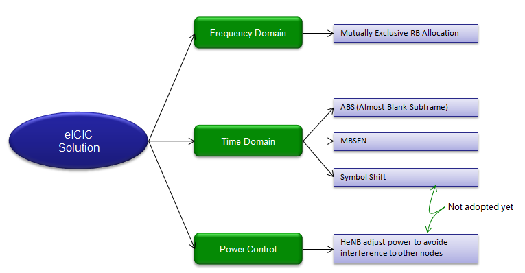
The ICIC methods of the LTE release 8 and 9 do not consider dominant interference scenarios of HetNets. In order to address such scenarios, the LTE-Advanced has been developing enhanced ICIC (eICIC) techniques, which can be classified into three categories:
-
Time-domain techniques: In time-domain techniques, the victim users are scheduled in time-domain resources where interference from other nodes is mitigated. Time-domain techniques employ subframe alignment and OFDM symbol shift.
-
Frequency-domain techniques: In frequency-domain techniques, control and reference signals are scheduled in reduced bandwidth, so that the signals of different cells are ensured to be orthogonal to one another. While frequency-domain orthogonality can be achieved in a static manner, it may also be implemented dynamically through victim UE detection.
-
Power control techniques: In power control techniques, femtocells employ power control schemes different from the one used in macrocells. The power control scheme can be designed by accounting for the following factors: the strongest macro eNB received power at a HeNB, path loss between a HeNB and macro UE, target signal-to-interference-plus-noise ratio (SINR) of home UE, and target SINR of macro UE.
Coordinated Multi-Point (CoMP) transmission/reception
Carrier aggregation and CoMP are the two most important techniques that boost the data rate of the LTEAdvanced to a new threshold. If we call CA a road of the LTE-Advanced, CoMP surely will be a car which the LTE-Advanced drives.
In traditional telecommunication systems, each UE will be basically served by only one base station (BS) at a moment. Signals come from other BS’s will become interference to the UE. When the UE moves to the cell edge, it will communicate with more than one BS’s to prepare for handover. However, it is still being served by its original BS. This is also the time when the UE receives strong interference, and data rate will be very low. The situation will become worse if the UE is moving with high speed.
Coordinated multipoint can be considered as a distributed MIMO system, in that geographically distributed nodes form multiple antennas and they cooperate to transmit to and/or receive from UE’s. CoMP has been studied as a solution for increasing the system throughput, especially at cell edge areas where inter-cell interference is severe with traditional approach. Due to the potential advantage, CoMP techniques received a lot of attention at the initiatory stage of the LTE-Advanced standardization. However, in practice, there are critical issues in CoMP, such as excessive feedback overhead, backhaul delay and burden, and interference channel estimation. Accordingly, the discussion on CoMP was suspended in release 10, but it is being discussed again in release 11.
Coordinated multipoint can be applied to both the DL and UL:
-
DL CoMP techniques can be classified according to the amount of information shared among cells. Joint processing is available when neighboring cells share transmit data as well as the channel state information. On the other hand, coordinated scheduling/coordinated beamforming (CS/CB) can be realized only if the channel state information and scheduling information are shared among eNB’s [44]; data sharing is not required.
-
For the case of UL, joint detection and interference prediction are considered.
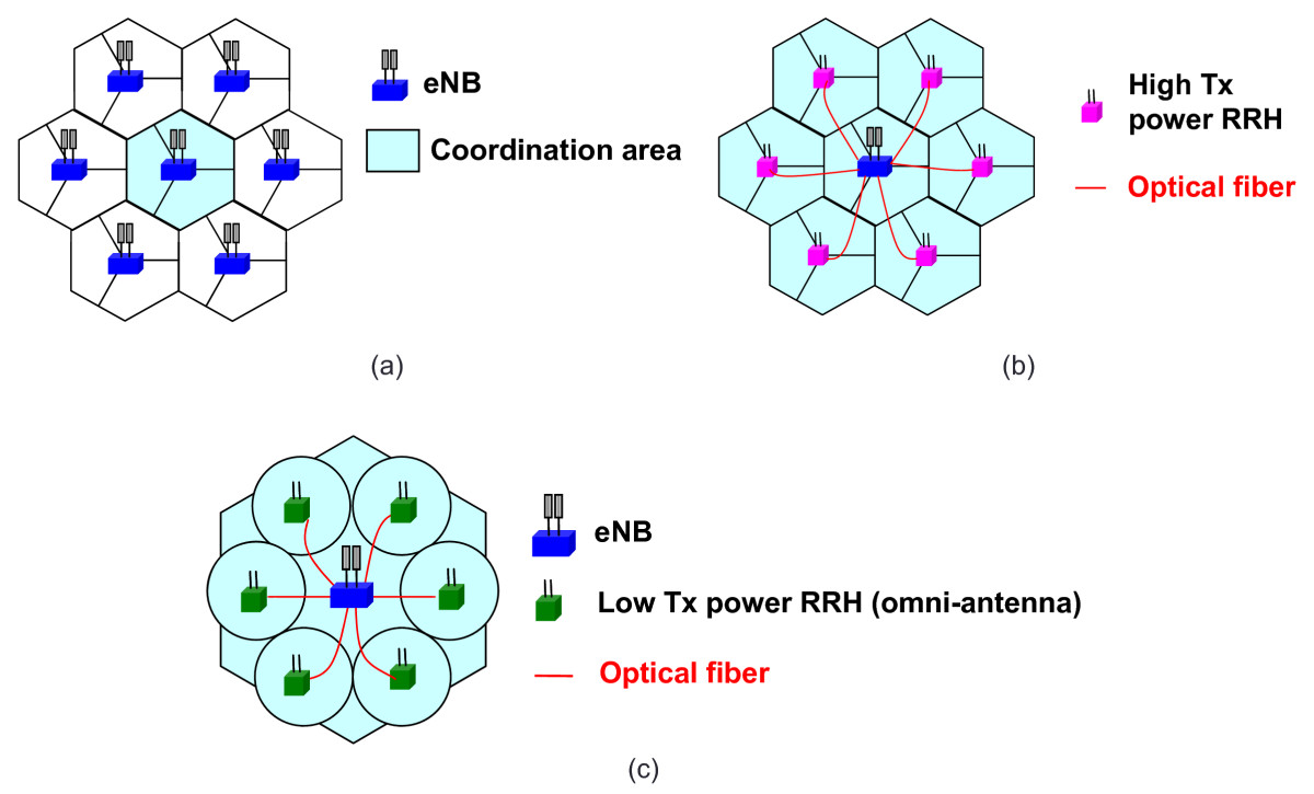
According to R1-110564 in 3GPP, CoMP techniques can be applied in three different scenarios [52], as illustrated in below figure. Currently, various CoMP schemes are being evaluated by several institutes under the scenarios. The scenarios of particular interest are the two scenarios with remote radio head (RRH), which ensures high capacity and low latency backhaul.
LTE/LTE-Advanced Key Technology
PSS, SSS and PBCH
Physical-layer Cell Identity (PCI)
There are 504 unique physical-layer cell identities. A physical-layer cell identity is defined by:
\[N^{cell}_{ID} = 3N^{(1)}_{ID} + N^{(2)}_{ID}\]where,
- \(N^{(1)}_{ID} \in [0, 167]\) is physical-layer cell-identity group and transmitted in Secondary Synchronization Signal (SSS);
- \(N^{(2)}_{ID} \in [0, 2]\) is physical-layer identity within the physical-layer cell-identity group and transmitted in Primary Synchronization Signal (PSS).
The physical-layer cell identity is only used in physical layer, which is different with the cell identity transmitted in SIB1, which is used to unambiguously identify a cell within a PLMN.
SystemInformationBlockType1
-> cellAccessRelatedInfo
   -> cellIdentity
Primary Synchronization Signal (PSS)
Generation of PSS Sequence
According to TS 36.211 S6.11.1.1, the sequence used for PSS is generated from a frequency-domain Zadoff-Chu sequence according to
\[d_u(n) = \begin{cases} e^{ -j \frac { {\pi} un(n+1)} {63} } & \text {n=0,1,..30} \\ e^{ -j \frac { {\pi} u(n+1)(n+2)} {63} } & \text {n=31,32,..61} \end{cases}\]where,
- the Zadoff-Chu root sequence index u is given by TS 36.211 Table 6.11.1.1-1 according to physical-layer identity \(N^{(2)}_{ID}\).
Mapping to REs
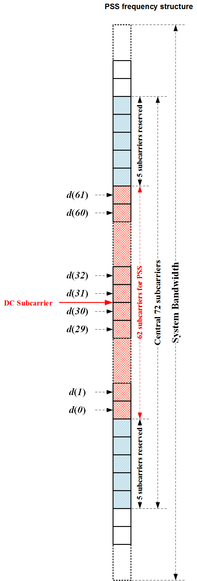
The sequence \(d(n)\) shall be mapped to the resource elements according to
\[a_{k,l} = d(n), n = 0,1,..61\]where,
- frequency-domain index is \(k = n - 31 + \frac { N^{DL}_{RB} N^{RB}_{sc} } {2}\)
- time-domain index l is
- for frame structure type 1, the last OFDM symbol in slots 0 and 10;
- for frame structure type 2, the third OFDM symbol in subframes 1 and 6.
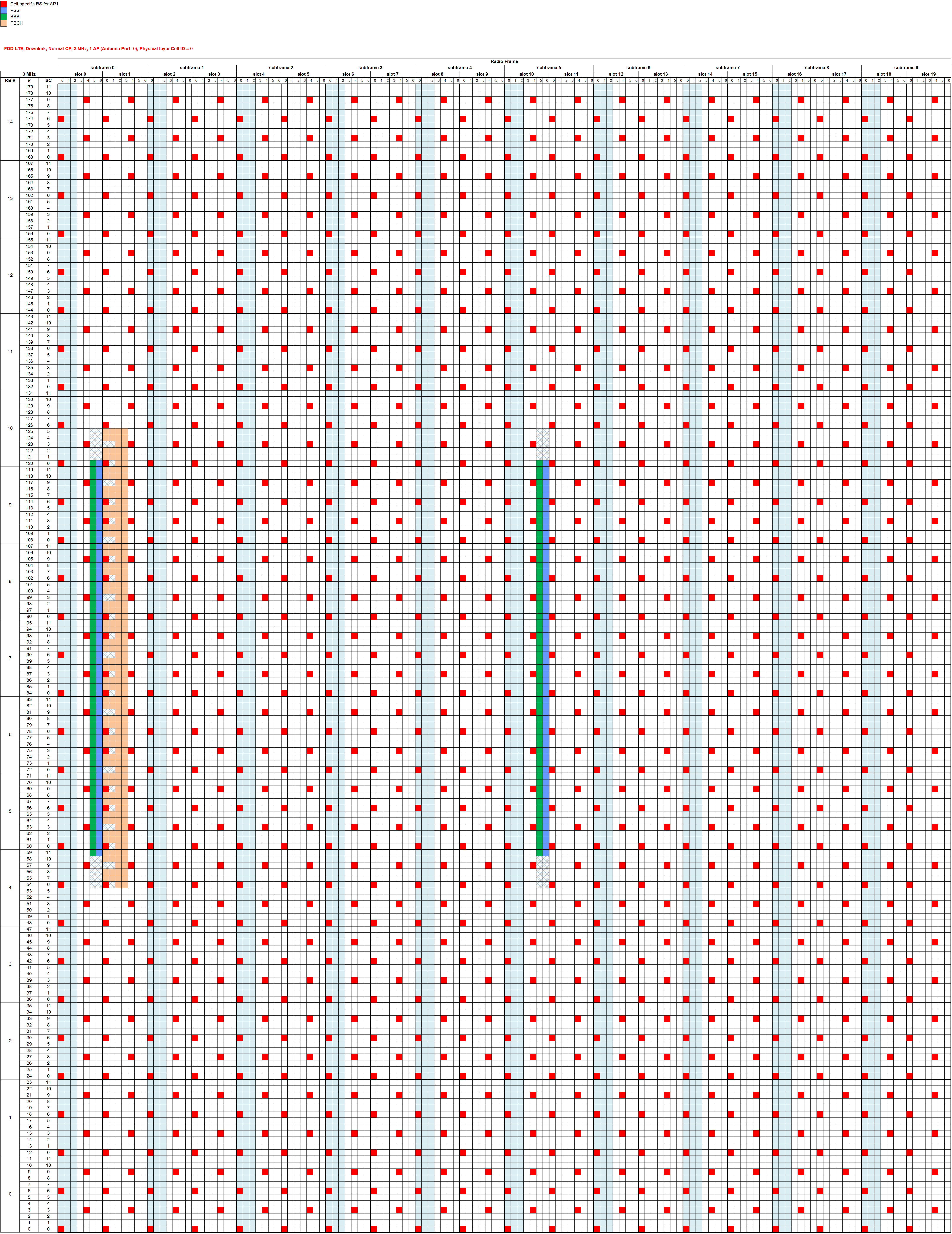
The following figure shows the PSS mapped resource elements in time-domain and frequency-domain respectively:
Note that the PSS sequences in every radio frame are the same, so the UE just can determine the slot timing when synchronization to eNB.
Also refer to LTE Resources by Sandesh Dhagle.
Secondary Synchronization Signal (SSS)
Refer to SSS Detection Method for Initial Cell Search in 3GPP LTE FDD/TDD Dual Mode Receiver
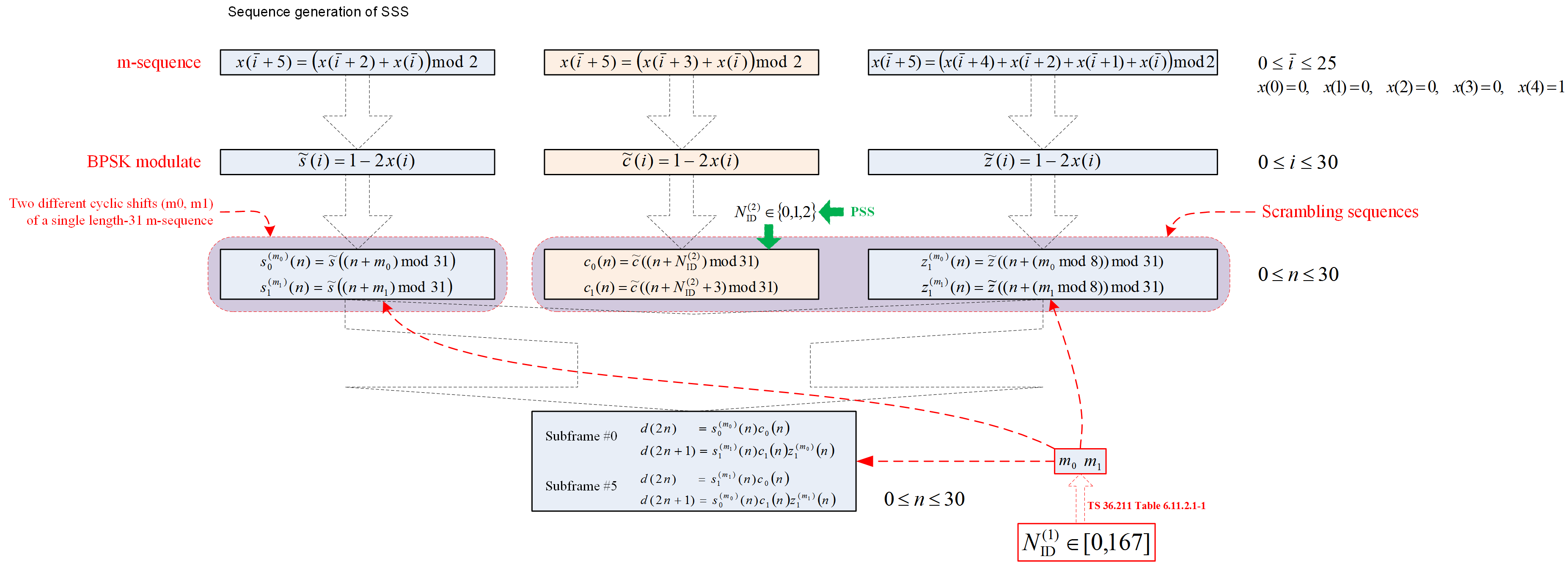
Generation of SSS Sequence
According to TS 36.211 S6.11.2.1, the sequence used for SSS is generated as shown in the following figure:
Mapping to REs
The sequence \(d(n)\) shall be mapped to the resource elements according to
\[a_{k,l} = d(n), n = 0,1,..61\]where,
- frequency-domain index is \(k = n - 31 + \frac { N^{DL}_{RB} N^{RB}_{sc} } {2}\)
- time-domain index is \(l = \begin{cases} N^{DL}_{symb}-2, & \text {in slots 0 and 10 for frame structure type1} \\ N^{DL}_{symb}-1, & \text {in slots 1 and 11 for frame structure type 2} \end{cases}\)
The following figure shows the SSS mapped resource elements in time-domain and frequency-domain respectively:
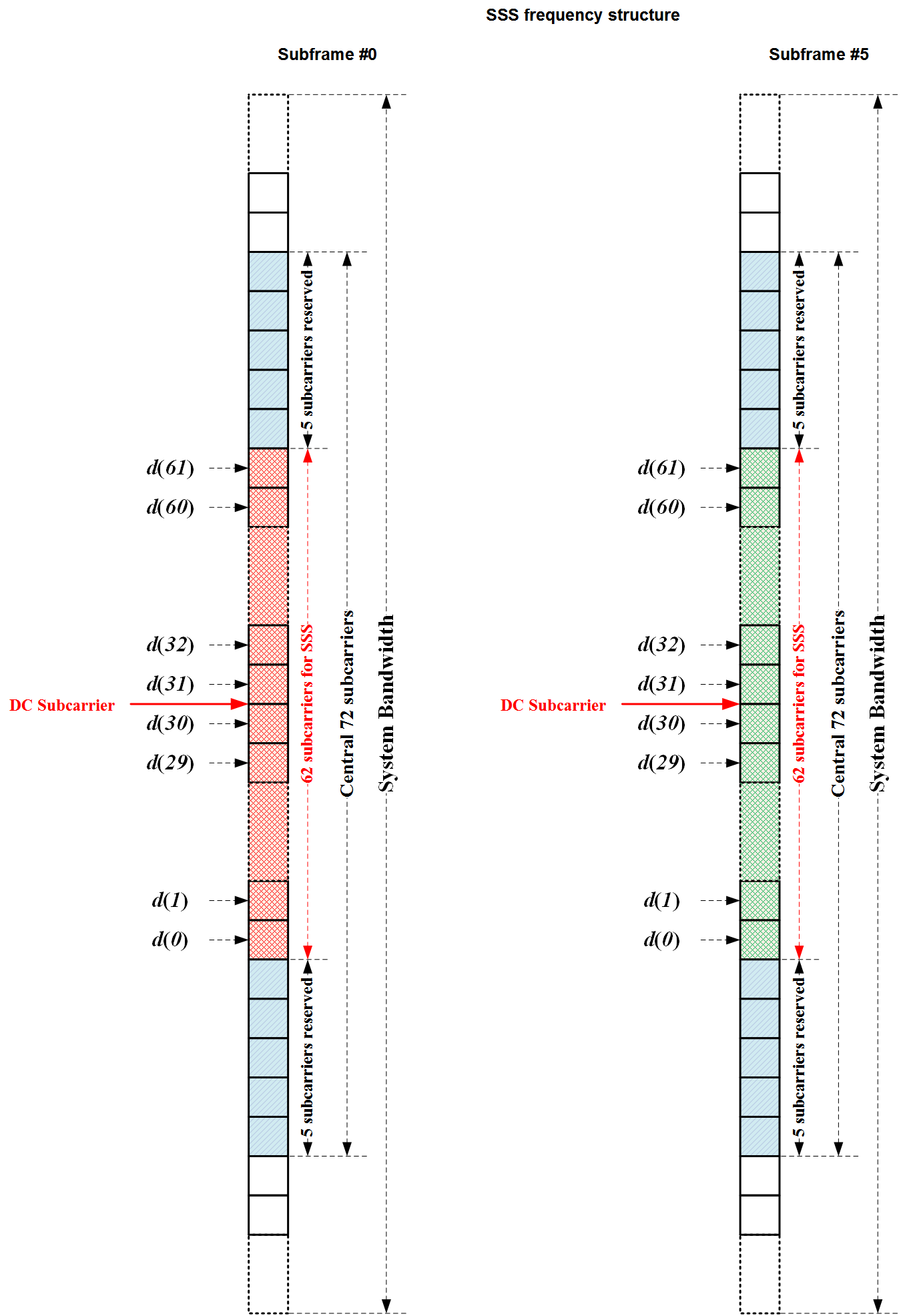
Note that the SSS sequences in subframe #0 and #5 are different, so the UE can determine the frame timing when synchronization to eNB.
Also refer to LTE Resources by Sandesh Dhagle.
Physical Broadcast Channel (PBCH)
The downlink Physical Broadcast Channel (PBCH) is used to transmit the Master Information Block (MIB) from logical channel BCH.
MIB from RRC
According to TS 36.331 S6.2.2, the MIB contains the following 24 bits system information:
MasterInformationBlock ::=  SEQUENCE {
    dl-Bandwidth        ENUMERATED {n6, n15, n25, n50, n75, n100},  // 3 bits
    phich-Config        PHICH-Config,                               // 3 bits
    systemFrameNumber   BIT STRING (SIZE (8)),                      // 8 bits
    spare               BIT STRING (SIZE (10))                      // 10 bits
}

PHICH-Config ::= SEQUENCE {
    phich-Duration      ENUMERATED {normal, extended},
    phich-Resource      ENUMERATED {oneSixth, half, one, two}
}
Q: Why is it necessary to have \(N_g\) in the MIB? Why does not include it in the MIB?
A: The reason that the UE needs to know the PHICH configuration at the very beginning of the system acquisition process is because of the “chicken-and-egg” problem. On one hand, the UE needs to decode PDCCH to know where to find SIB on PDSCH. On the other hand, PDCCH and PHICH and PCFICH share the resources in the control region of a subframe and the set of the available resources for PDCCH depends on the PHICH configuration (PCFICH resources are fixed and known).
Q: The System Frame Number (SFN) in LTE has 10 bit length, but why is it only 8 bits in MIB->systemFrameNumber?
A: In LTE, the SFN has 10 bit length, and the MSB 8 bits are transmitted in MIB->systemFrameNumber. The LSB 2 bits are blind-detected by UE according to the position of radio frame in 40 ms PBCH window, that’s, the LSB 2 bits are 00, 01, 02, 03 for the radio frame corresponding to the first, second, third and fourth radio frame in 40 ms PBCH window, respectively. The blind-detected is based on the scrambling sequence \(c(i)\) in TS 36.211 S6.6.1.
BCCH Process in RLC
A TM RLC entity can be configured to deliver/receive RLC PDUs through the BCCH logical channel. Refer to TS 36.322 S4.2.1.1.1.
BCH Process in MAC
Refer to TS 36.321 S4.2.1.
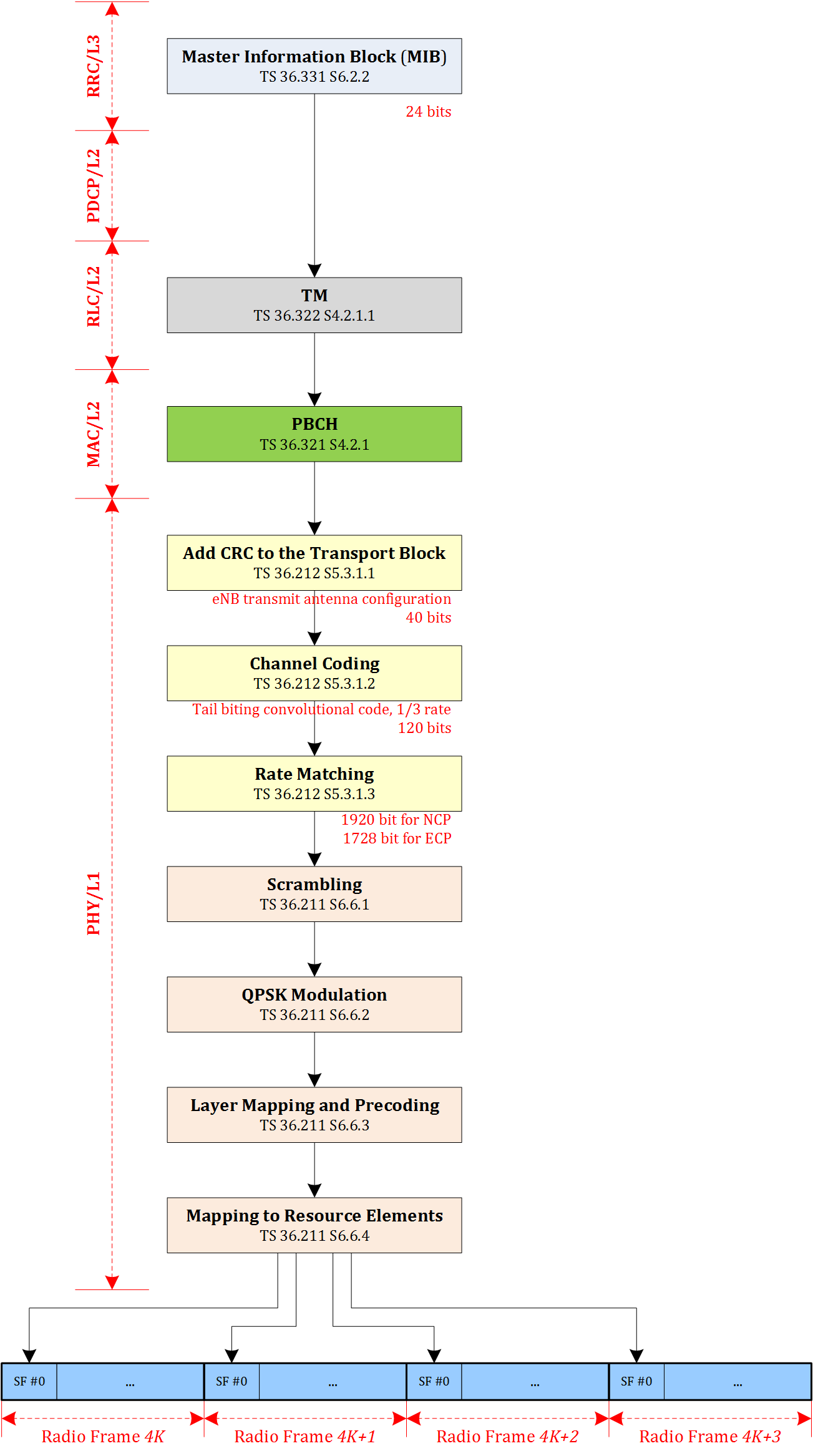
PBCH Process in PHY
According to TS 36.212 S5.3.1, the following steps are processed in PHY about the PBCH:
-
Add CRC to the transport block
16 bits CRC is appended to transport block, so the output of this step is 40 bits sequence.
Note that the number of antenna ports is transmitted in CRC part of BCH transport block, refer to TS 36.212 Table 5.3.1.1-1. That’s, UE can blind-detect the number of antenna ports by decoding BCH transport block.
-
Channel coding
The channel coding scheme is tail biting convolutional coding with 1/3 coding rate, so the output of this step is 120 bits sequence.
-
Rate matching
According to TS 36.211 S6.6.1, the number of bits transmitted on the physical broadcast channel is 1920 for normal cyclic prefix (NCP) and 1728 for extended cyclic prefix (ECP), so the output of this step is 1920 and 1728 bits sequence for NCP and ECP respectively.
-
Scrambling
According to TS 36.211 S6.6.1, the scrambling sequence shall be initialised with \(c_{init} = N^{cell}_ID\) in each radio frame fulfilling \(n_f % 4 == 0\). That’s why UE can blind-detect the LSB 2 bits of system frame number. Then, UE gets the system frame number by combining it with the MSB 8 bits from MIB->systemFrameNumber.
-
Modulation
QPSK. The output of this step is 960 bits sequence for NCP, and 864 bits sequence for ECP.
-
Layer Mapping and Precoding
Refer to TS 36.211 S6.6.3.
-
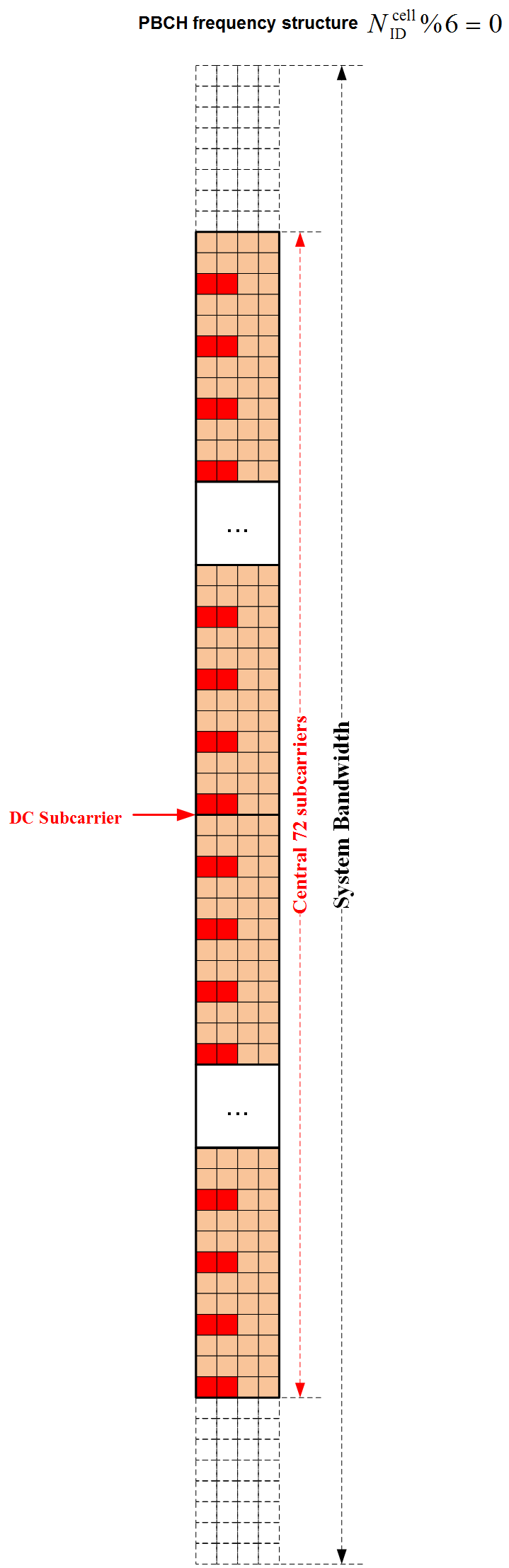
Mapping to REs
The block of complex-valued symbols for each antenna port is transmitted during 4 consecutive radio frames starting in each radio frame fulfilling \(n_f mod 4 == 0\). That’s why it takes 4 radio frames to read MIB.
The following figure shows the PBCH mapped resource elements in time-domain and frequency-domain respectively:
Also refer to LTE Resources by Sandesh Dhagle.
Synchronisation Procedure
The following figure shows the synchronisation procedure when UE try to access to LTE:
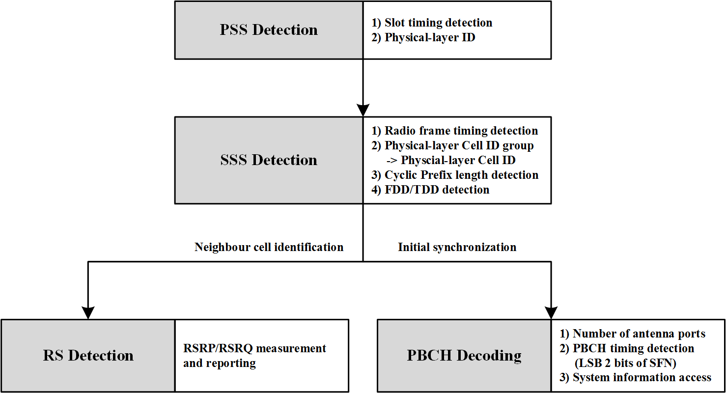
-
PSS detection
UE gets the following information when detection PSS:
- Synchronisation to slot timing
- Physical-layer identity \(N^{(2)}_{ID}\)
-
SSS detection
UE gets the following information when detection SSS:
- Synchronisation to radio frame timing.
- Physical-layer cell-identity group \(N^{(1)}_{ID}\). Then, UE gets the physical-layer cell identity by the formula in section Physical-layer Cell Identity (PCI).
- Cyclic prefix length and system type FDD/TDD according to the position between PSS and SSS.
-
PBCH decoding
UE gets the following information when detection SSS:
- Number of antenna ports according to CRC of MIB transport block
- System information contained in MIB, refer to MIB from RRC.
Downlink Reference Signals
There are three kind of reference signals on downlink:
Cell-specific Reference Signal
Cell-specific reference signals shall be transmitted in all downlink subframes in a cell supporting non-MBSFN transmission. In case the subframe is used for transmission with MBSFN, only the first two OFDM symbols in a subframe can be used for transmission of cell-specific reference symbols.
Cell-specific reference signals are transmitted on one or several of antenna ports 0 to 3.
Cell-specific reference signals are defined for \(\delta f = 15 kHz\) only.
Sequence Generation
Refer to TS 36.211 S6.10.1.1.
Mapping to REs
In time domain, the location of cell-specific reference signals is fixed, that’s on symbol 0 and \(N^{DL}_{symb}-3\) for antenna ports 0 and 1, symbol 1 for antenna ports 2 and 3.
In frequency domain, the location of cell-specific reference signals is distributed accross the system bandwidth and related to physical-layer cell identity \(N^{cell}_{ID}\).
The following figure shows the cell-specific reference signals of LTE-FDD with 3MHz system bandwidth, normal CP and antenna port 0:
Refer to the following sheets in R8_TS36.XXX_LTE_PHY_Parameters_v2.xlsx:
- 36.211 S6.7.4 PCFICH REs
- LTE-FDD, DL, NCP, 1 AP, All BW
- LTE-FDD, DL, NCP, 2 AP, All BW
- LTE-FDD, DL, NCP, 4 AP, All BW
- LTE-FDD, DL, NCP, 4 AP, 1.4MHz
- LTE-FDD, DL, NCP, 4 AP, 3MHz
- LTE-FDD, DL, NCP, 4 AP, 5MHz
- LTE-FDD, DL, NCP, 4 AP, 15MHz
- LTE-FDD, DL, NCP, 4 AP, 20MHz
- LTE-FDD, DL, ECP, 1 AP, All BW
- LTE-FDD, DL, ECP, 2 AP, All BW
- LTE-FDD, DL, ECP, 4 AP, All BW
- LTE-TDD, DL, NCP, 1 AP, All BW
- LTE-TDD, DL, NCP, 2 AP, All BW
- LTE-TDD, DL, NCP, 4 AP, All BW
- LTE-TDD, DL, ECP, 1 AP, All BW
- LTE-TDD, DL, ECP, 2 AP, All BW
- LTE-TDD, DL, ECP, 4 AP, All BW
Also refer to LTE Resources by Sandesh Dhagle.
MBSFN Reference Signal
MBSFN reference signals shall only be transmitted in subframes allocated for MBSFN transmissions. MBSFN reference signals are transmitted on antenna port 4.
MBSFN reference signals are defined for extended cyclic prefix only.
Sequence Generation
Refer to TS 36.211 E-UTRA - Physical Channels and Modulation, S6.10.2.1.
Mapping to REs
Refer to TS 36.211 E-UTRA - Physical Channels and Modulation, S6.10.2.2.
UE-specific Reference Signal
RRC Configurations
The following configuration from TS 36.331 points to one of Transmission modes defined in TS 36.213 S7.1.
AntennaInfoDedicated
-> transmissionMode
The following configuration from TS 36.331 defines whether the UE supports PDSCH transmission mode 7 for FDD, refer to TS 36.306 S4.3.4.2.
UE-EUTRA-Capability
-> phyLayerParameters
   -> ue-SpecificRefSigsSupported
Sequence Generation
Refer to TS 36.211 E-UTRA - Physical Channels and Modulation, S6.10.3.1.
Mapping to REs
Refer to TS 36.211 E-UTRA - Physical Channels and Modulation, S6.10.3.2.
Physical Control Format Indicator CHannel (PCFICH)
The physical control format indicator channel (PCFICH) carries information about the number of OFDM symbols used for transmission of PDCCHs in a subframe. The set of OFDM symbols possible to use for PDCCH in a subframe is given by TS 36.211 Table 6.7-1.
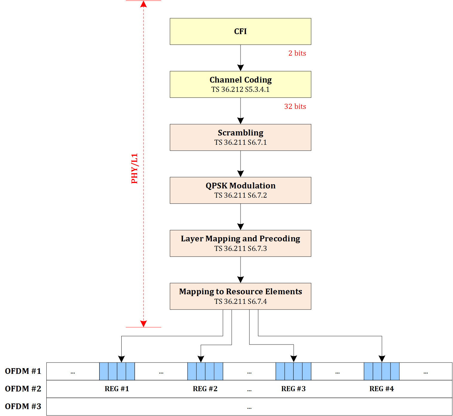
The following figure shows the process of CFI:
How to determine CFI value
Refer to TS 36.212 S5.3.4 and TS 36.211 Table 6.7-1.
Channel Coding
Refer to TS 36.212 S5.3.4.
Scrambling
Refer to TS 36.211 S6.7.1
Modulation
Refer to TS 36.211 S6.7.2
Layer Mapping and Precoding
Refer to TS 36.211 S6.7.3
Mapping to REs
According to TS 36.211 S6.7.4, the CFI is mapped to the four resource-element groups in the first OFDM symbol in a downlink subframe with the representative resource-element.
Refer to the following sheets in R8_TS36.XXX_LTE_PHY_Parameters_v2.xlsx:
- 36.211 S6.7.4 PCFICH REs
- LTE-FDD, DL, NCP, 1 AP, All BW
- LTE-FDD, DL, NCP, 2 AP, All BW
- LTE-FDD, DL, NCP, 4 AP, All BW
- LTE-FDD, DL, NCP, 4 AP, 1.4MHz
- LTE-FDD, DL, NCP, 4 AP, 3MHz
- LTE-FDD, DL, NCP, 4 AP, 5MHz
- LTE-FDD, DL, NCP, 4 AP, 15MHz
- LTE-FDD, DL, NCP, 4 AP, 20MHz
- LTE-FDD, DL, ECP, 1 AP, All BW
- LTE-FDD, DL, ECP, 2 AP, All BW
- LTE-FDD, DL, ECP, 4 AP, All BW
- LTE-TDD, DL, NCP, 1 AP, All BW
- LTE-TDD, DL, NCP, 2 AP, All BW
- LTE-TDD, DL, NCP, 4 AP, All BW
- LTE-TDD, DL, ECP, 1 AP, All BW
- LTE-TDD, DL, ECP, 2 AP, All BW
- LTE-TDD, DL, ECP, 4 AP, All BW
Also refer to LTE Resources by Sandesh Dhagle.
Physical Hybrid ARQ Indicator CHannel (PHICH)
PHICH Groups and Orthogonal Sequences
The PHICH carries the hybrid-ARQ ACK/NAK. Multiple PHICHs mapped to the same set of resource elements constitute a PHICH group, where PHICHs within the same PHICH group are separated through different orthogonal sequences.
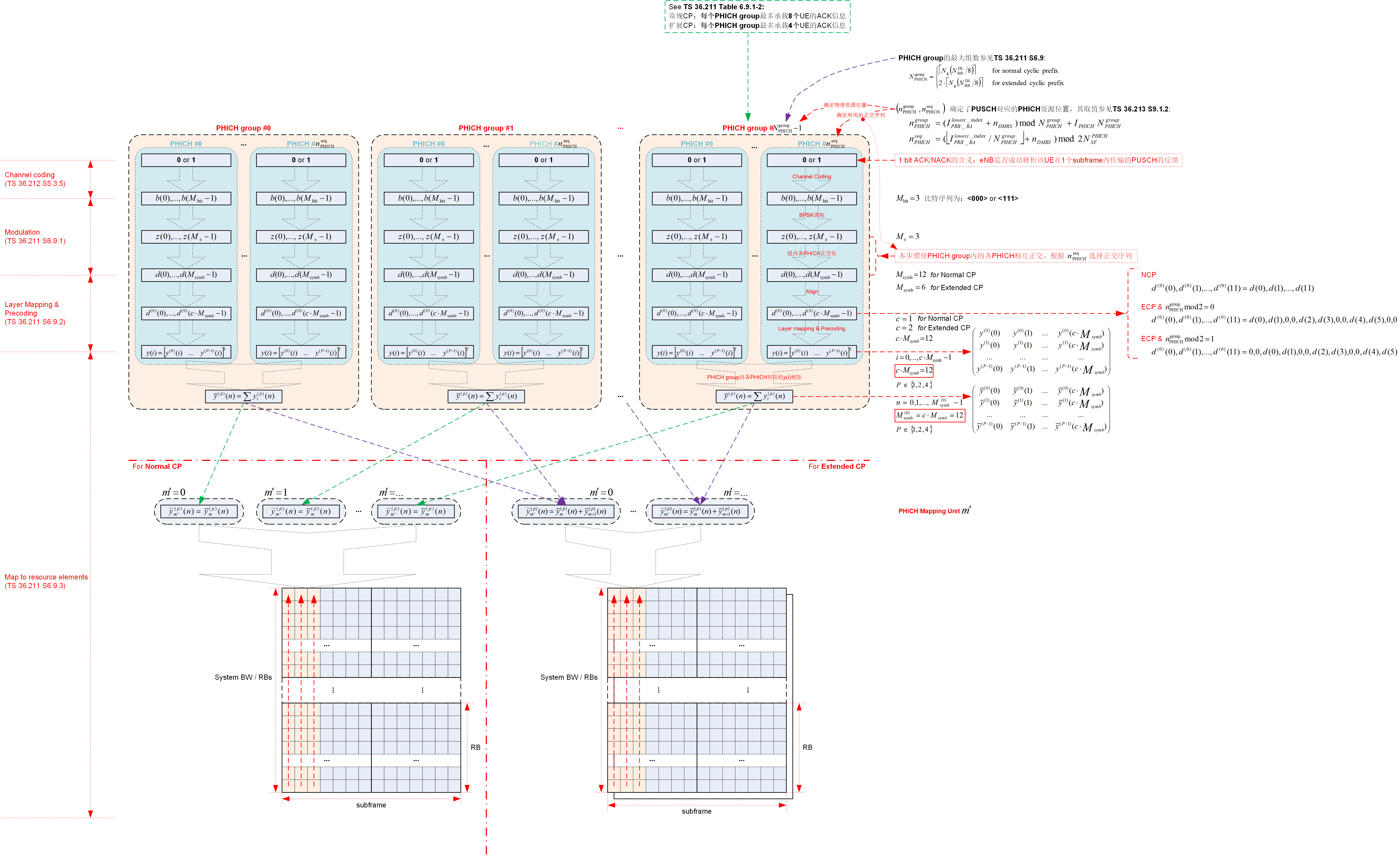
A PHICH resource is identified by the index pair:
\[(n^{group}_{PHICH}, n^{seq}_{PHICH})\]where,
- \(n^{group}_{PHICH}\) and \(n^{seq}_{PHICH}\) are given by TS 36.213 S9.1.2;
- \(n^{group}_{PHICH}\) is the PHICH group number, \(n^{group}_{PHICH} \in [0, N^{group}_{PHICH}-1]\), where \(N^{group}_{PHICH}\) is calculated in TS 36.211 S6.9;
- \(n^{seq}_{PHICH}\) is the orthogonal sequence index within the group, refer to TS 36.211 Table 6.9.1-2.
Channel Coding
Refer to TS 36.212 S5.3.5.
Modulation
Modulation scheme for PHICH is BPSK, refer to TS 36.211 S6.9.1.
Resource Group Alignment, Layer Mapping and Precoding
Refer to TS 36.211 S6.9.2.
Mapping to REs
Refer to the following sheets in R8_TS36.XXX_LTE_PHY_Parameters_v2.xlsx:
- LTE-FDD, DL, NCP, 1 AP, All BW
- LTE-FDD, DL, NCP, 2 AP, All BW
- LTE-FDD, DL, NCP, 4 AP, All BW
- LTE-FDD, DL, NCP, 4 AP, 1.4MHz
- LTE-FDD, DL, NCP, 4 AP, 3MHz
- LTE-FDD, DL, NCP, 4 AP, 5MHz
- LTE-FDD, DL, NCP, 4 AP, 15MHz
- LTE-FDD, DL, NCP, 4 AP, 20MHz
- LTE-FDD, DL, ECP, 1 AP, All BW
- LTE-FDD, DL, ECP, 2 AP, All BW
- LTE-FDD, DL, ECP, 4 AP, All BW
- LTE-TDD, DL, NCP, 1 AP, All BW
- LTE-TDD, DL, NCP, 2 AP, All BW
- LTE-TDD, DL, NCP, 4 AP, All BW
- LTE-TDD, DL, ECP, 1 AP, All BW
- LTE-TDD, DL, ECP, 2 AP, All BW
- LTE-TDD, DL, ECP, 4 AP, All BW
Also refer to LTE Resources by Sandesh Dhagle.
Physical Downlink Control CHannel (PDCCH)
Flow Diagram of PDCCH
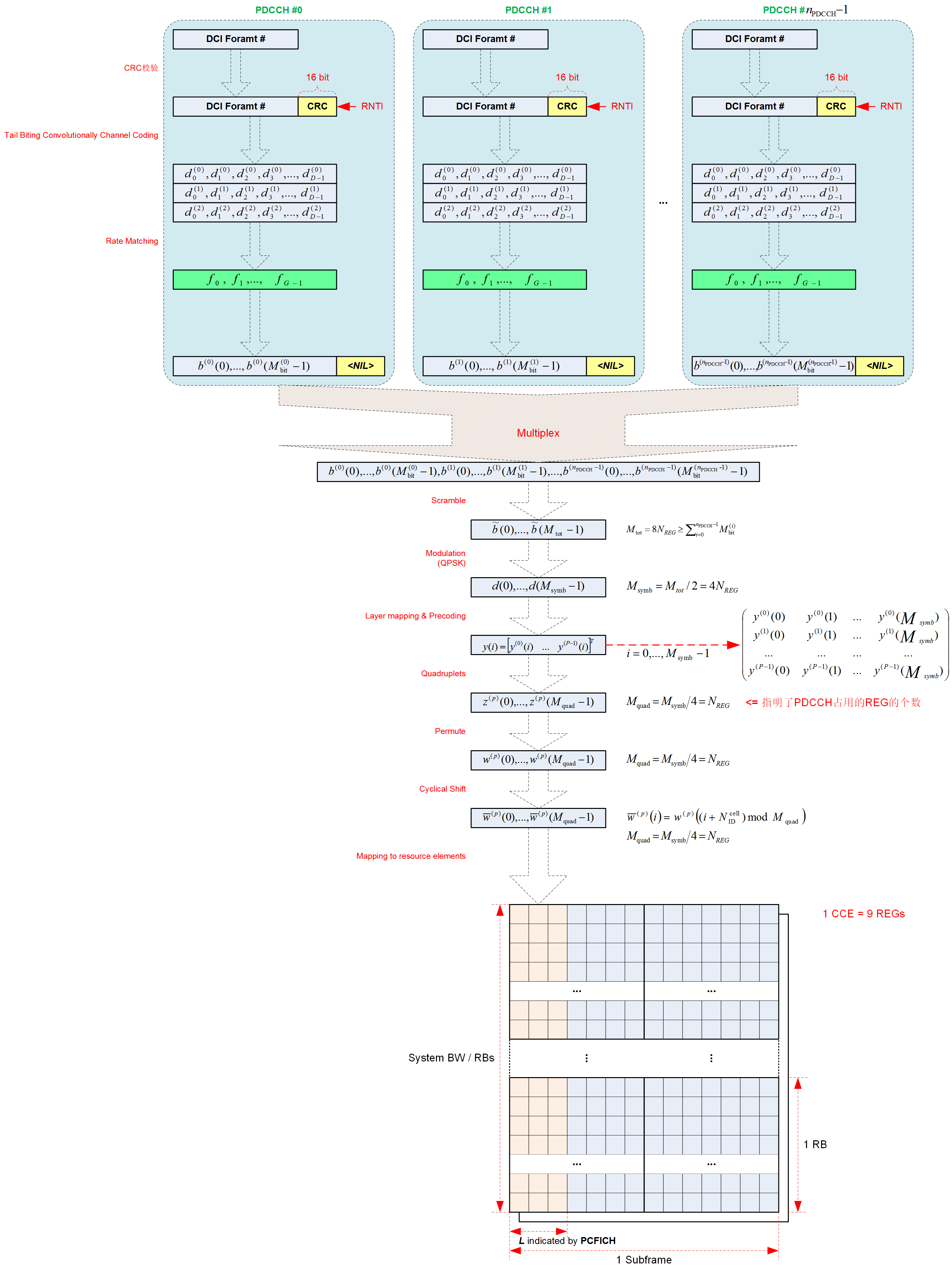
Downlink Control Information (DCI)
Refer to TS 36.212 S5.3.3.1.
A DCI transports downlink or uplink scheduling information, or uplink power control commands for one RNTI. The RNTI is implicitly encoded in the CRC, refer to CRC Attachment.
DCI Formats
-
DCI Format 0
- Uplink
- 上行共享信道
- Function: 用于上行 PUSCH 的调度
- Specs: TS 36.213 Table 8-3, 8-5, 8-6
-
DCI Format 1
- Downlink
- 单码字
- Function: 用于下行单码字 PDSCH 的调度
- Transmission Mode: 1, 2, 7
- Specs: TS 36.213 Table 7.1-5, 7.1-6
-
DCI Format 1A
- Downlink
- 单码字
- Function: 用于下行单码字 PDSCH 和随机接入流程的紧凑型调度
- Transmission Mode: All TM, SI-RNTI, P-RNTI, RA-RNTI
- Specs: TS 36.213 Table 7.1-1, 7.1-2, 7.1-3, 7.1-5, 7.1-6, 7.1-7, 8-4
-
DCI Format 1B
- Downlink
- 单码字
- Function: 用于预编码的下行单码字 PDSCH 的紧凑型调度
- Transmission Mode: 6
- Specs: TS 36.213 Table 7.1-5
-
DCI Format 1C
- Downlink
- 单码字
- Function: 用于下行单码字 PDSCH 的更紧凑模型调度
- Transmission Mode: SI-RNTI, P-RNTI, RARNTI
- Specs: TS 36.213 Table 7.1-1, 7.1-2, 7.1-3
-
DCI Format 1D
- Downlink
- 单码字
- Function: 用于具有预编码与功率偏移信息的下行单码字 PDSCH 的紧凑型调度
- Transmission Mode: 5
- Specs: TS 36.213 Table 7.1-5
-
DCI Format 2
- Downlink
- 双码字
- Function: 用于闭环空间复用情况下的双码字 PDSCH 的调度
- Transmission Mode: 4
- Specs: TS 36.213 Table 7.1-5, 7.1-6
-
DCI Format 2A
- Downlink
- 双码字
- Function: 用于开环空间复用情况下的双码字 PDSCH 的调度
- Transmission Mode: 3
- Specs: TS 36.213 Table 7.1-5, 7.1-6
-
DCI Format 2B
- Downlink
- 双码字
- Function: 用于双层的双码字 PDSCH 的调度
- Transmission Mode: 8
- Specs: Rel 9 TS 36.213 Table 7.1-5, 7.1-6
-
DCI Format 3
- Uplink
- 功率控制信息
- Function: 用于传输一组用户的 PUCCH 和 PUSCH 的功率控制信息,其中功率控制信息采用 2 比特指示
- Specs: TS 36.213 Table 8-7, 8-8
-
DCI Format 3A
- Uplink
- 功率控制信息
- Function: 用于传输一组用户的 PUCCH 和 PUSCH 的功率控制信息,其中功率控制信息采用 1 比特指示
- Specs: TS 36.213 Table 8-7, 8-8
DCI Length before CRC Attachment
According to TS 36.212 SS5.3.3.1, the length of DCI formats before CRC attachment are shown in the following table:
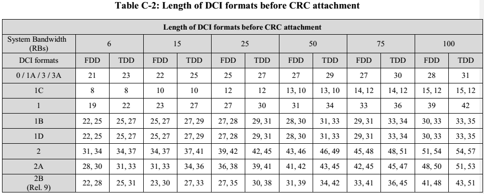
NOTE1:上表中 DCI format 1C 行中存在两个长度值(在某些系统带宽下) ,这是根据 \(N_{gap}\) 区分的,前者为 \(N_{gap} = N_{gap,1}\),后者为 \(N_{gap} = N_{gap,2}\);
NOTE2:上表中 DCI format 1B/1D 行中存在两个长度值,这是根据基站天线数的不同进行区分的,参见 TS 36.212 Table 5.3.3.1.3A-2, Table 5.3.3.1.4A-1,前者为 AP=2,后者为 AP=4;
NOTE3:上表中 DCI format 2/2A 行中存在两个长度值,这是根据基站天线数的不同(基站天线数不同,则对应的 Precoding information 域的宽度不同) 进行区分的,参见 TS 36.212 Table 5.3.3.1.5-3, Table 5.3.3.1.5A-1,前者为 AP=2,后者为 AP=4。
NOTE4:由上表可知, DCI format 1B/1D 的长度相等。
NOTE5:上表中 DCI format 2B 行中存在两个长度值,这是根据传输的 TB 块的数目不同进行区分的,前者为 1 TB,后者为 2 TBs。
CRC Attachment
The CRC parity bits are 16 bits. The CRC parity bits may be scrambled with Antenna selection mask (refer to TS 36.212 Table 5.3.3.2-1) and corresponding RNTI (refer to TS 36.212 S5.3.3.1) if UE transmit antenna selection is configured and applicable, refer to TS 36.212 S5.3.3.2, TS 36.213 S8.7 and the following configuration from higher layer:
PhysicalConfigDedicated
-> antennaInfo
   -> explicitValue     AntennaInfoDedicated
      -> ue-TransmitAntennaSelection
         -> setup ENUMERATED {closedLoop, openLoop}
Channel Coding
The coding scheme for DCI is Tail biting convolutional coding with 1/3 coding rate, refer to TS 36.212 S5.3.3.3.
Rate Matching
Refer to TS 36.212 S5.3.3.4.
Multiplexing and Scrambling
Refer to TS 36.211 S6.8.2.
Modulation
Modulation scheme for PDCCH is QPSK, refer to TS 36.211 S6.8.3.
Layer Mapping and Precoding
Refer to TS 36.211 S6.8.4.
Mapping to REs
Refer to TS 36.211 S6.8.5.
Also refer to the following sheets in R8_TS36.XXX_LTE_PHY_Parameters_v2.xlsx:
- LTE-FDD, DL, NCP, 1 AP, All BW
- LTE-FDD, DL, NCP, 2 AP, All BW
- LTE-FDD, DL, NCP, 4 AP, All BW
- LTE-FDD, DL, NCP, 4 AP, 1.4MHz
- LTE-FDD, DL, NCP, 4 AP, 3MHz
- LTE-FDD, DL, NCP, 4 AP, 5MHz
- LTE-FDD, DL, NCP, 4 AP, 15MHz
- LTE-FDD, DL, NCP, 4 AP, 20MHz
- LTE-FDD, DL, ECP, 1 AP, All BW
- LTE-FDD, DL, ECP, 2 AP, All BW
- LTE-FDD, DL, ECP, 4 AP, All BW
- LTE-TDD, DL, NCP, 1 AP, All BW
- LTE-TDD, DL, NCP, 2 AP, All BW
- LTE-TDD, DL, NCP, 4 AP, All BW
- LTE-TDD, DL, ECP, 1 AP, All BW
- LTE-TDD, DL, ECP, 2 AP, All BW
- LTE-TDD, DL, ECP, 4 AP, All BW
Also refer to LTE Resources by Sandesh Dhagle.
NB-IoT
NB-IoT is a new 3GPP radio-access technology in the sense that it is not fully backward compatible with existing 3GPP devices.
The normative phase of NB-IoT work item in 3GPP started in September 2015 and the core specifications complete in June 2016. Commercial launch of NB-IoT products and services is expected to be around the end of 2016 and the beginning of 2017.
RF Performance
- TS36.101: Evolved Universal Terrestrial Radio Access (E-UTRA); User Equipment (UE) radio transmission and reception
- TS36.141: Evolved Universal Terrestrial Radio Access (E-UTRA); Base Station (BS) conformance testing
Signal-to-Noise Ratio (SNR)
According to Signal-to-Noise Ratio (SNR), SNR is a measure used in science and engineering that compares the level of a desired signal to the level of background noise. SNR is defined as the ratio of signal power to the noise power, often expressed in decibels. A ratio higher than 1:1 (greater than 0 dB) indicates more signal than noise.
Signal-to-noise ratio is defined as the ratio of the power of a signal (meaningful information) to the power of background noise (unwanted signal):
\[SNR = \frac {P_{signal}} {P_{noise}}\]where, P is average power. Both signal and noise power must be measured at the same or equivalent points in a system, and within the same system bandwidth.
Because many signals have a very wide dynamic range, signals are often expressed using the logarithmic decibel scale:
\[SNR_{dB} = 10 ∙ log_{10} (\frac {P_{signal}} {P_{noise}}) = 10 ∙ log_{10} (P_{signal}) - 10 ∙ log_{10} (P_{noise})\]Improving SNR in practice
All real measurements are disturbed by noise. This includes electronic noise, but can also include external events that affect the measured phenomenon — wind, vibrations, gravitational attraction of the moon, variations of temperature, variations of humidity, etc., depending on what is measured and of the sensitivity of the device. It is often possible to reduce the noise by controlling the environment. Otherwise, when the characteristics of the noise are known and are different from the signals, it is possible to filter it or to process the signal.
For example, it is sometimes possible to use a lock-in amplifier to modulate and confine the signal within a very narrow bandwidth and then filter the detected signal to the narrow band where it resides, thereby eliminating most of the broadband noise. When the signal is constant or periodic and the noise is random, it is possible to enhance the SNR by averaging the measurement. In this case the noise goes down as the square root of the number of averaged samples.
Additionally, internal noise of electronic systems can be reduced by low-noise amplifiers.
Error Vector Magnitude (EVM)
Error Vector Magnitude (EVM) is a measure used to quantify the performance of a digital radio transmitter or receiver. A signal sent by an ideal transmitter or received by a receiver would have all constellation points precisely at the ideal locations, however various imperfections in the implementation (such as carrier leakage, low image rejection ratio, phase noise etc.) cause the actual constellation points to deviate from the ideal locations. Informally, EVM is a measure of how far the points are from the ideal locations.
Noise, distortion, spurious signals, and phase noise all degrade EVM, and therefore EVM provides a comprehensive measure of the quality of the radio receiver or transmitter for use in digital communications. Transmitter EVM can be measured by specialized equipment, which demodulates the received signal in a similar way to how a real radio demodulator does it. One of the stages in a typical phase-shift keying demodulation process produces a stream of I-Q points which can be used as a reasonably reliable estimate for the ideal transmitted signal in EVM calculation.
Definition of EVM
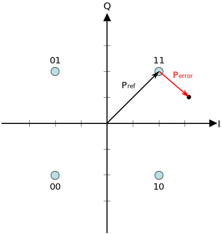
An error vector is a vector in the I-Q plane between the ideal constellation point and the point received by the receiver. In other words, it is the difference between actual received symbols and ideal symbols. The average amplitude of the error vector, normalized to peak signal amplitude, is the EVM. For the percentage format, Root Mean Square (RMS) average is used.
The Error Vector Magnitude (EVM) is equal to the ratio of the amplitude of the error vector to the Root Mean Square (RMS) amplitude of the reference. It is defined in dB as:
\[EVM(dB) = 20 ∙ log_{10} (\frac {P_{error}} {P_{reference}})\]where \(P_{error}\) is the RMS amplitude of the error vector. For single carrier modulations, \(P_{reference}\) is, by convention, the amplitude of the outermost (highest power) point in the reference signal constellation. More recently, for multi-carrier modulations, \(P_{reference}\) is defined as the reference constellation average power.
EVM is defined as a percentage in a compatible way:
\[EVM(\%) = \sqrt{\frac {P_{error}} {P_{reference}}} × 100\%\]with the same definitions.
EVM, as conventionally defined for single carrier modulations, is a ratio of a mean amplitude to a peak amplitude. Because the relationship between the peak and mean signal power is dependent on constellation geometry, different constellation types (e.g. 16-QAM and 64-QAM), subject to the same mean level of interference, will report different EVM values.
EVM, as defined for multi carrier modulations, is arguably the more satisfactory measurement because it is a ratio of two mean powers and is insensitive to the constellation geometry. In this form, EVM is closely related to Modulation error ratio, the ratio of mean signal power to mean error power.
Measurement of EVM
ACLR
CFR and DPD
References
- ShareTechnote
- ShareTechnote Index
- LTE Dictionary on ShareTechnote
- LTE Full Stack on ShareTechnote
- LTE PDCP Layer on ShareTechnote
- LTE RLC Layer on ShareTechnote
- LTE MAC Layer on ShareTechnote
- LTE PHY Processing on ShareTechnote
- LTE Quick Reference on ShareTechnote
- LTE Basic Procedure on ShareTechnote
- Typical Packet Call Processing on ShareTechnote
- LTE Network Architecture on ShareTechnote
- LTE SAE on ShareTechnote
- 3GLTEinfo
- 4G-Portal
- LTE Network Architecture
- GSM, LTE, UMTS and IMS Call Flows
- Digital Standard EUTRA/LTE from Rohde Schwarz
- LTE Resources by Sandesh Dhagle
- TS 36.211 E-UTRA - Physical Channels and Modulation
- PBCH (Physical Broadcast Channel) on ShareTechnote
- PSS (Primary Synchronization Channel) on ShareTechnote
- SSS (Secondary Synchronization Channel) on ShareTechnote
- SSS Detection Method for Initial Cell Search in 3GPP LTE FDD/TDD Dual Mode Receiver
- TS 36.211 E-UTRA - Physical Channels and Modulation, S6.10
- Downlink Reference Signal on ShareTechnote
- Cell Specific Reference Signal on ShareTechnote
- MatLab Toolbox for Cell Specific Reference Signal on ShareTechnote
- TS 36.212 E-UTRA - Multiplexing and channel coding, section 5.3.4
- TS 36.211 E-UTRA - Physical Channels and Modulation, section 6.7
- CFI (Control Format Indicator) on ShareTechnote
- PCFICH (Physical Control Format Indicator Channel) on ShareTechnote
- MatLab Toolbox for PCFICH on ShareTechnote
- TS 36.213 E-UTRA - Physical layer procedures, section 9.1.2
- TS 36.212 E-UTRA - Multiplexing and channel coding, section 5.3.5
- TS 36.211 E-UTRA - Physical Channels and Modulation, section 6.9
- PHICH/PHICH Group on ShareTechnote
- MatLab Toolbox for PHICH on ShareTechnote
- TS 36.213 E-UTRA - Physical layer procedures, section 8.7 UE Transmit Antenna Selection
- TS 36.212 E-UTRA - Multiplexing and channel coding, section 5.3.3 Downlink control information
- TS 36.211 E-UTRA - Physical Channels and Modulation, section 6.8 Physical downlink control channel
- Signal-to-Noise Ratio (SNR)
- EVM on Wikipedia
- EVM Calculation for Broadband Modulated Signals